AVR32DEV1
Note
This port is functional but very basic. There are configurations for NSH and the OS test.
This is a port of NuttX to the Atmel AVR32DEV1 board and compatible with MCUZone UC3B-CPU board depicted here:
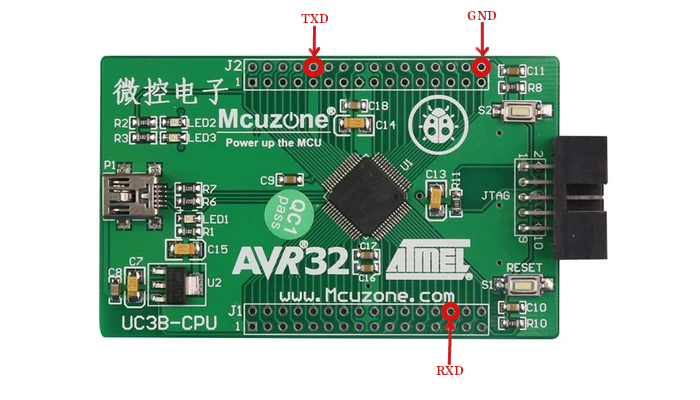
The MCUZone AVR32DEV1 board.
This board is based on the Atmel AT32UC3B0256 MCU and uses a specially patched version of the GNU toolchain: The patches provide support for the AVR32 family. That patched GNU toolchain is available only from the Atmel website.
Features
AVR32 AT32UC3B0256 microcontroller
mini-USB Connector
Power LED (LED1)
MCU controllable LEDs: LED2 and LED3
S1/RESET and S2 buttons (S2 accessible to user)
12MHz (main clock) and 32KHz for RTC
Serial Console
The board uses by default the USART1 as serial console. The pins PB2 (TXD) and PA24 (RXD) are used for USART1.
This way you need to connect a USB/Serial adapter to get access to the NuttShell. Connect the TXD from your USB/Serial to the RXD of the board, and the RXD from USB/Serial to the TXD of the board.
There is another detail about the baudrate, you need to use 57600 8n1.
The AVR32DEV1 board has no RS-232 drivers or connectors on board. An off-board MAX232 module was used (search for MAX232 if you want to find one). The MAX232 board was connected as follows:
In boards/avr/at32uc3/avr32dev/include/board.h:
#define PINMUX_USART1_RXD   PINMUX_USART1_RXD_1
#define PINMUX_USART1_TXD   PINMUX_USART1_TXD_1
In arch/avr/src/at32uc3/at32uc3b_pinmux.h:
#define PINMUX_USART1_RXD_1 (GPIO_PERIPH | GPIO_FUNCD | GPIO_PORTA | 17)
#define PINMUX_USART1_TXD_1 (GPIO_PERIPH | GPIO_FUNCA | GPIO_PORTA | 23)
PA17 and PA23 are available from the AVR32DEV1:
FUNC |
GPIO |
PIN |
Header 16X2 (J1) |
MX232 Board |
|---|---|---|---|---|
RXD |
PA17 |
PIN37 |
Pin 5 |
PIN4 RXD (5V TTL/CMOS) |
TXD |
PA23 |
PIN47 |
Pin 15 |
PIN3 TXD (5V TTL/CMOS) |
– |
– |
– |
– |
PIN2 GND |
– |
– |
– |
– |
PIN1 VCC (5V) |
Voltage on GPIO Pins with respect to ground for TCK, RESET_N, PA03-PA08, PA11-PA12, PA18-PA19, PA28-PA31: 0.3 to 3.6V
Other Pins: -0.3 to 5.5V
The 5V are taken from another USB port (using the 5V power cable that normally provides the extra current needed by my USB IDE drive).
GPIO Pin Configuration
For crystals, JTAG, and USB:
Pin |
ID |
Function |
|---|---|---|
PIN 30 |
PA11 |
XIN32 |
PIN 31 |
PA12 |
XOUT32 |
PIN 35 |
PA15 |
EVTO (JTAG) |
PIN 39 |
PA18 |
X1IN |
PIN 40 |
PA19 |
X1OUT |
PIN 61 |
PA26 |
ID (USB) |
All GPIO pins are brought out through connectors J1 (PINS 33-64) and J2 (PINS 1-32).
Note
There seems to be some difference in labeling for OSC0 and OSC1 between MCUZone.com and Atmel.
Oscillator pinout:
QFP48 Pin |
QFP64 Pin |
ID |
Osc. Pin |
AVR32DEV1 Label |
|---|---|---|---|---|
30 |
39 |
PA18 |
XIN0 |
X1IN (12MHz) |
– |
41 |
PA28 |
XIN1 |
PA28 (no crystal) |
22 |
30 |
PA11 |
XIN32 |
XIN32 (32KHz) |
31 |
40 |
PA19 |
XOUT0 |
X1OUT (12Mhz) |
– |
42 |
PA29 |
XOUT1 |
PA29 (no crystal) |
23 |
31 |
PA12 |
XOUT32 |
XOUT32 (32 Khz) |
Note
These crystal inputs/outputs are analog signals and my assumption is that they need no pin multiplexing setting to enable them for the external crystal function.
Warning
There is no support for OSC1.
Note
There are solder pads for the 32KHz OSC32, but the crystal is not populated on my board. Therefore, the RTC will have to run from the (uncalibrated) RCOSC.
Installation
Linux, macOS or Cygwin on Windows can be used for the development environment. The source has been built only using the GNU toolchain (see below). Other toolchains will likely cause problems. Testing was performed using the Cygwin environment.
GNU Toolchains
Atmel Toolchain
The build logic in these directories assume that you are using the GNU toolchain with the Atmel patches. The patch file, pre-patched tool sources,and pre-built binaries are available from the Atmel website.
CONFIG_AVR32_AVRTOOLSW=y  # Use the windows version
CONFIG_AVR32_AVRTOOLSL=y  # Use the Linux version
Note
The NuttX builtroot cannot be used to build the AVR32 toolchain. This is because the Atmel patches that add support for the AVR32 are not included in the NuttX buildroot.
AVR32 Toolchain Builder
A third option is to build the toolchain yourself. For macOS and Linux systems, this Makefile will build a complete gcc-4.4.3 toolchain:
https://github.com/jsnyder/avr32-toolchain
By default the toolchain installs into ${HOME}/avr-32-tools-<somedate> and
the bin subdirectory must be added to your path before compiling.
Building NuttX
Because this build uses a native Windows toolchain and the native Windows tools do not understand Cygwin’s symbolic links, the NuttX make system does something weird: It copies the configuration directories instead of linking to them (it could, perhaps, use the NTFS ‘mklink’ command, but it doesn’t).
A consequence of this is that you can easily get confused when you edit a file in one of the “linked” directories, re-build NuttX, and then not see your changes when you run the program. That is because build is still using the version of the file in the copied directory, not your modified file! To work around this annoying behavior, do the following when you re-build:
$ make clean_context all # Remove and re-copy all of the directories, then make all
$ doisp.sh               # Load the code onto the board.
Flashing
AVR32 Bootloader
Boot Sequence
“An AVR UC3 part having the bootloader programmed resets as any other part at 80000000h. Bootloader execution begins here. The bootloader first performs the boot process to know whether it should start the USB DFU ISP or the application. If the tested conditions indicate that the USB DFU ISP should be started, then execution continues in the bootloader area, i.e. between 80000000h and 80002000h, else the bootloader launches the application at 80002000h.”
Link Address
The linker scripts (ld.script) assume that you are using the DFU bootloader. The bootloader resides at 0x8000:0000 and so the ld.script files link the application to execute after the bootloader at 0x8000:2000. To link so that NuttX boots directly without using the bootloader, change the flash definition from:
flash (rxai!w) : ORIGIN = 0x80002000, LENGTH = 256K - 8K
to:
flash (rxai!w) : ORIGIN = 0x80000000, LENGTH = 256K
Or to use the MSC bootloader:
flash (rxai!w) : ORIGIN = 0x80008000, LENGTH = 256K - 32K
Entering the ISP
In order to use the USB port to download the FLASH(ISP), you need to use the S3(PA13) to make CPU return to boot status. In this mode, the on chip bootloader will run, making the ISP possible.
BatchISP
Unlike other Atmel parts, the AVR32 will not work with the FLIP GUI program.
Instead, you must use the command-line loader call BatchISP. If need to download
FLIP from the atmel.com website, install the USB driver in the FLIP usb
directory. Then in the bin directory where you installed FLIP, you will also
find batchisp.exe.
Note
You will need to set the PATH environment variable to include the path to
the BatchISP bin directory.
Notes from “AVR32 UC3 USB DFU Bootloader” (doc7745.pdf)
“To launch BatchISP, open a command prompt. Windows or Cygwin command prompt can be used provided that the bin folder of the FLIP installation directory is in the PATH (Windows’ or Cygwin’s) environment variable. When running BatchISP on AT32UC3xxxxx, the target part has to be specified with -device at32uc3xxxxx and the communication port with -hardware usb. Commands can then be placed after -operation. These commands are executed in order. BatchISP options can be placed in a text file invoked using -cmdfile rather than on the command line.
- “BatchISP works with an internal ISP buffer per target memory. These ISP
buffers can be filled from several sources. All target operations (program, verify, read) are performed using these buffers.”
The following BatchISP command line will erase FLASH, write the nuttx binary into FLASH, and reset the AVR32. This command line is available in the script
config/avr32dev1/tools/doisp.sh:$ batchisp -device at32uc3b0256 -hardware usb -operation erase f memory flash \ blankcheck loadbuffer nuttx.elf program verify start reset 0“BatchISP main commands available on AT32UC3xxxxx are:
ASSERT { PASS | FAIL } changes the displayed results of the following operations according to the expected behavior.
ONFAIL { ASK | ABORT | RETRY | IGNORE } changes the interactive behavior of BatchISP in case of failure.
WAIT <Nsec> inserts a pause between two ISP operations.
ECHO <comment> displays a message.
ERASE F erases internal flash contents, except the bootloader.
MEMORY { FLASH | SECURITY | CONFIGURATION | BOOTLOADER | SIGNATURE | USER } selects a target memory on which to apply the following operations.
ADDRANGE <addrMin> <addrMax> selects in the current target memory an address range on which to apply the following operations.
BLANKCHECK checks that the selected address range is erased.
FILLBUFFER <data> fills the ISP buffer with a byte value.
LOADBUFFER { <in_elffile> | <in_hexfile> } loads the ISP buffer from an input file.
PROGRAM programs the selected address range with the ISP buffer.
VERIFY verifies that the selected address range has the same contents as the ISP buffer.
READ reads the selected address range to the ISP buffer.
SAVEBUFFER <out_hexfile> { HEX386 | HEX86 } saves the ISP buffer to an output file.
START { RESET | NORESET } 0 starts the execution of the programmed application with an optional hardware reset of the target.
“The AT32UC3xxxxx memories made available by BatchISP are:
FLASH: This memory is the internal flash array of the target, including the bootloader protected area. E.g. on AT32UC3A0512 (512-kB internal flash), addresses from 0 to 0x7FFFF can be accessed in this memory.
SECURITY: This memory contains only one byte. The least significant bit of this byte reflects the value of the target Security bit which can only be set to 1. Once set, the only accepted commands will be ERASE and START. After an ERASE command, all commands are accepted until the end of the non-volatile ISP session, even if the Security bit is set.
CONFIGURATION: This memory contains one byte per target general-purpose fuse bit. The least significant bit of each byte reflects the value of the corresponding GP fuse bit.
BOOTLOADER: This memory contains three bytes concerning the ISP: the ISP version in BCD format without the major version number (always 1), the ISP ID0 and the ISP ID1.
SIGNATURE: This memory contains four bytes concerning the part: the product manufacturer ID, the product family ID, the product ID and the product revision.
USER: This memory is the internal flash User page of the target, with addresses from 0 to 0x1FF.
“For further details about BatchISP commands, launch
batchisp -hor see the help files installed with FLIP …”
Configurations
Configurations can be selected using:
$ tools/configure.sh avr32dev1:<config>
Where <config> is one of the following configurations.
nsh
Configures the NuttShell (nsh). The Configuration enables only the serial
NSH interface.
ostest
This configuration directory, performs a simple OS test using ostest.
Note
Round-robin scheduling is disabled in this test because the RR test in examples/ostest declares data structures that are too large for the poor little uc3 SRAM.