ESP32-LyraT V4.3
The ESP32-LyraT development board is a hardware platform designed for the dual-core ESP32 audio applications, e.g., Wi-Fi or BT audio speakers, speech-based remote controllers, smart-home appliances with audio functionality(ies), etc. You can find the board schematic here.
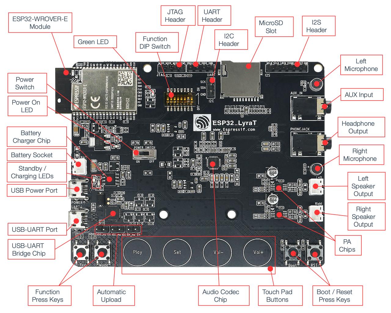
ESP32-LyraT V4.3 Board Layout
The block diagram below presents main components of the ESP32-LyraT.
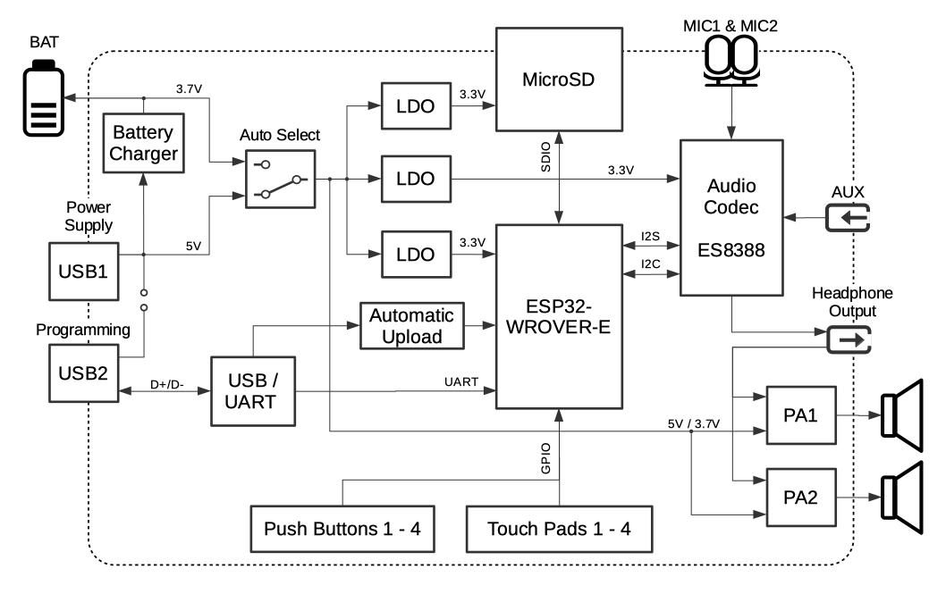
ESP32-LyraT V4.3 Electrical Block Diagram
Features
ESP32-WROVER-E Module
JTAG Interface
MicroSD Slot
Audio Codec Chip
Battery Charger Chip
Touch Pad Buttons
Serial Console
UART0 is, by default, the serial console. It connects to the on-board CP2102N bridge and is available on the USB connector.
It will show up as /dev/ttyUSB[n] where [n] will probably be 0.
Audio Codec
This is currently unsupported. Drivers still in development.
The Audio Codec Chip, ES8388, is a low power stereo audio codec with a headphone amplifier. It consists of 2-channel ADC, 2-channel DAC, microphone amplifier, headphone amplifier , digital sound effects, analog mixing and gain functions. It is interfaced with ESP32-WROVER-E Module over I2S and I2S buses to provide audio processing in hardware independently from the audio application.
It also provides:
Onboard microphone connected to IN1 of the Audio Codec Chip.
Auxiliary input socket connected to IN2 (left and right channel) of the Audio Codec Chip. Use a 3.5 mm stereo jack to connect to this socket.
Output socket to connect headphones with a 3.5 mm stereo jack.
Note
The socket may be used with mobile phone headsets and is compatible with OMPT standard headsets only. It does work with CTIA headsets. Please refer to Phone connector (audio) on Wikipedia.
Output socket to connect a speaker. The 4-ohm and 3-watt speaker is recommended. The pins have a 2.00 mm / 0.08” pitch.
The development board uses two mono Class D amplifier ICs, model number NS4150 with maximum output power of 3W and operating voltage from 3.0V to 5.25V. The audio input source is the digital-to-analog converter (DAC) output of the ES8388. Audio output supports two external speakers. An optional audio output is a pair of headphones feed from the same DACs as the amplifier ICs.
To switch between using headphones and speakers, the board provides a digital input signal to detect when a headphone jack is inserted and a digital output signal to enable or disable the amplifier ICs. In other words selection between speakers and headphones is under software control instead of using mechanical contacts that would disconnect speakers once a headphone jack is inserted.
Note
The codec implementation on the LyraT board was validated using 16-bit, 44.1kHz WAV files. Other configurations might not work as expected.
SD card
The development board supports a MicroSD card in SPI/1-bit/4-bit modes, and can store or play audio files in the MicroSD card. Note that JTAG cannot be used and should be disconnected by setting Function DIP Switch when MicroSD Card is in operation, because some of signals are shared by both devices.
Enable MicroSD Card in 1-wire Mode
Set Function DIP Switch to:
DIP SW |
Position |
|---|---|
1 |
OFF |
2 |
OFF |
3 |
OFF |
4 |
OFF |
5 |
OFF |
6 |
OFF |
7 |
OFF 1 |
8 |
n/a |
AUX Input detection may be enabled by toggling the DIP SW 7 ON. Note that the AUX Input signal pin should not be be plugged in when the system powers up. Otherwise the ESP32 may not be able to boot correctly.
In this mode:
JTAG functionality is not available
Vol- touch button is available for use with the API
Enable MicroSD Card in 4-wire Mode
Set Function DIP Switch to:
DIP SW |
Position |
|---|---|
1 |
ON |
2 |
ON |
3 |
OFF |
4 |
OFF |
5 |
OFF |
6 |
OFF |
7 |
OFF |
8 |
n/a |
In this mode:
JTAG functionality is not available
Vol- touch button is not available for use with the API
AUX Input detection from the API is not available
JTAG
Provides access to the JTAG interface of ESP32-WROVER-E Module. It may be used for debugging, application upload, as well as implementing several other functions.
Enable JTAG
Set Function DIP Switch to:
DIP SW |
Position |
|---|---|
1 |
OFF |
2 |
OFF |
3 |
ON |
4 |
ON |
5 |
ON |
6 |
ON |
7 |
ON |
8 |
n/a |
In this mode:
MicroSD Card functionality is not available, remove the card from the slot
Vol- touch button is not available for use with the API
AUX Input detection from the API is not available
Battery
The board has a constant current & constant voltage linear charger for single cell lithium-ion batteries AP5056. Used for charging of a battery connected to the Battery Socket over the Micro USB Port.
Note
Please verify if polarity on the battery plug matches polarity of the socket as marked on the board’s soldermask besides the socket.
Note
The Power On Switch does not affect/disconnect the Li-ion battery charging.
Pin Mapping
Several pins ESP32 module are allocated to the on board hardware. Some of them, like GPIO0 or GPIO2, have multiple functions. Please refer to the table below.
GPIO Pin |
Type |
Function Definition |
|---|---|---|
SENSOR_VP |
I |
Audio Rec (PB) |
SENSOR_VN |
I |
Audio Mode (PB) |
IO32 |
I/O |
Audio Set (TP) |
IO33 |
I/O |
Audio Play (TP) |
IO27 |
I/O |
Audio Vol+ (TP) |
IO13 |
I/O |
JTAG MTCK, MicroSD D3, Audio Vol- (TP) |
IO14 |
I/O |
JTAG MTMS, MicroSD CLK |
IO12 |
I/O |
JTAG MTDI, MicroSD D2, Aux signal detect |
IO15 |
I/O |
JTAG MTDO, MicroSD CMD |
IO2 |
I/O |
Automatic Upload, MicroSD D0 |
IO4 |
I/O |
MicroSD D1 |
IO34 |
I |
MicroSD insert detect |
IO0 |
I/O |
Automatic Upload, I2S MCLK |
IO5 |
I/O |
I2S SCLK |
IO25 |
I/O |
I2S LRCK |
IO26 |
I/O |
I2S DSDIN |
IO35 |
I |
I2S ASDOUT |
IO19 |
I/O |
Headphone jack insert detect |
IO22 |
I/O |
Green LED indicator |
IO21 |
I/O |
PA Enable output |
IO18 |
I/O |
I2C SDA |
IO23 |
I/O |
I2C SCL |
(TP) - touch pad
(PB) - push button
There are several pin headers available to connect external components, check the state of particular signal bus or debug operation of ESP32. Note that some signals are shared.
UART Header / JP2
Header Pin |
|
|---|---|
1 |
3.3V |
2 |
TX |
3 |
RX |
4 |
GND |
I2S Header / JP4
I2C Header Pin |
ESP32 Pin |
|
|---|---|---|
1 |
MCLK |
GPIO0 |
2 |
SCLK |
GPIO5 |
1 |
LRCK |
GPIO25 |
2 |
DSDIN |
GPIO26 |
3 |
ASDOUT |
GPIO35 |
3 |
GND |
GND |
I2C Header / JP5
I2C Header Pin |
ESP32 Pin |
|
|---|---|---|
1 |
SCL |
GPIO23 |
2 |
SDA |
GPIO18 |
3 |
GND |
GND |
JTAG Header / JP7
ESP32 Pin |
JTAG Signal |
|
|---|---|---|
1 |
MTDO / GPIO15 |
TDO |
2 |
MTCK / GPIO13 |
TCK |
3 |
MTDI / GPIO12 |
TDI |
4 |
MTMS / GPIO14 |
TMS |
Note
JTAG cannot be used if MicroSD Card is enabled.
Configurations
All of the configurations presented below can be tested by running the following commands:
$ ./tools/configure.sh esp32-lyrat:<config_name>
$ make flash ESPTOOL_PORT=/dev/ttyUSB0 -j
Where <config_name> is the name of board configuration you want to use, i.e.: nsh, buttons, wifi…
Then use a serial console terminal like picocom configured to 115200 8N1.
audio
This configuration uses the I2S0 peripheral and the ES8388 audio codec present on the LyraT board to play an audio file streamed over HTTP while connected to a Wi-Fi network.
Simple HTTP server
Prepare a PCM-encoded (.wav) audio file with 16 bits/sample (sampled at 44.1kHz). This file must be placed into a folder in a computer that could be accessed on the same Wi-Fi network the ESP32 will be connecting to.
Python provides a simple HTTP server. cd to the audio file folder on the PC and run:
$ python3 -m http.server

Serving HTTP on 0.0.0.0 port 8000 (http://0.0.0.0:8000/)
Look for your PC IP address and test playing the prepared audio on your browser:
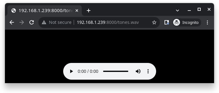
After successfully built and flashed, connect the board to the Wi-Fi network:
$ nsh> wapi psk wlan0 mypasswd 3
$ nsh> wapi essid wlan0 myssid 1
$ nsh> renew wlan0
Once connected, open NuttX’s player and play the file according to its file name and the IP address of the HTTP server (For example tones.wav and 192.168.1.239:8000, respectively):
$ nsh> nxplayer
$ nxplayer> play http://192.168.1.239:8000/tones.wav
Note
The codec implementation on the LyraT board was validated using 16-bit, 44.1kHz WAV files. Other configurations might not work as expected.
sdmmc_spi
This configuration is used to mount a FAT/FAT32 SD Card into the OS’ filesystem. For the ESP32-LyraT, make sure the DIP switches 1 and 2 are turned to the ON position.
The SD slot number, SPI port number and minor number can be modified in Application Configuration → NSH Library.
To access the card’s files, execute the following commands:
nsh> mount -t vfat /dev/mmcsd0 /mnt
nsh> ls /mnt/
/mnt:
song_16_88200_2ch.wav
song_16_96000_2ch.wav
song_24_44100_2ch.wav
song_32_44100_2ch.wav
nsh
Basic NuttShell configuration (console enabled in UART0, exposed via USB connection by means of the CP2102N bridge, at 115200 bps).
nxrecorder
This configuration is used to record raw audio from the ES8388 audio codec through the I2S0 peripheral to a FAT32 SD Card. By default the audio is recorded from the on-board microphones. For the ESP32-LyraT, make sure the DIP switches 1 and 2 are turned to the ON position. To record audio, execute the following commands:
nsh> mount -t vfat /dev/mmcsd0 /mnt
nsh> nxrecorder
nxrecorder> recordraw /mnt/record.raw
nxrecorder> stop
To play the recorded audio, import the raw data into Audacity and set the encoding to signed 16-bit PCM, the sample rate to 44.1kHz and the number of channels to 2.
rtptools
RTP Tools is a set of small applications that can be used for processing RTP data.
rtpplay: play back RTP sessions recorded byrtpdumprtpsend: generate RTP packets from the textual description, generated by hand orrtpdumprtpdump: parse and print RTP packets, generating output files suitable forrtpplayandrtpsendrtptrans: RTP translator between unicast and multicast networks
This application is able to receive RTP packets and write the content to a FIFO. nxplayer then reads
from the FIFO, enabling using NuttX as a RTP receiver for audio applications.
This is particularly useful to stream uncompressed audio through Wi-Fi to remote speakers.
Connect to your Network
Connect the ESP32-LyraT board to your network in order to be able to receive RTP packets:
nsh> wapi psk wlan0 mypasswd 3
nsh> wapi essid wlan0 myssid 1
nsh> renew wlan0
nsh> ifconfig
wlan0   Link encap:Ethernet HWaddr aa:bb:cc:dd:ff:ee at RUNNING mtu 1504
        inet addr:192.168.1.38 DRaddr:192.168.1.1 Mask:255.255.255.0

            IPv4   TCP   UDP  ICMP
Received     00d5  0000  00d4  0000
Dropped      0001  0000  0000  0000
IPv4        VHL: 0000   Frg: 0000
Checksum   0000  0000  0000  ----
TCP         ACK: 0000   SYN: 0000
            RST: 0000  0000
Type       0000  ----  ----  0000
Sent         0002  0000  0002  0000
Rexmit     ----  0000  ----  ----
Please, check your device’s IP (192.168.1.38 in this example):
RTP packets will be sent to it.
Sending Audio through pulseaudio
pulseaudio is able to send RTP packets through the network:
pactl load-module module-null-sink sink_name=rtp format=s16be channels=2 rate=44100 sink_properties="device.description='RTP'"
pactl load-module module-rtp-send source=rtp.monitor format=s16le destination_ip=192.168.1.38 port=46998
The loaded sink is used to send PC audio through RTP, using the 192.168.1.38:46998
(boards’s IP in this example, please adjust accordingly).
Receiving the RTP packets
RTP packets will be written to a FIFO: create the FIFO and run rtpdump
on background:
nsh> mkfifo temp
nsh> rtpdump -F payload -o temp /46998 &
rtpdump [31:100]
Playing Audio
Finally, run nxplayer to play from the FIFO:
nsh> nxplayer
NxPlayer version 1.05
h for commands, q to exit

nxplayer> playraw temp 2 16 44100
This board contains the ES8388 audio codec. Please attach your headphones to listen to the content streamed through the Wi-Fi in CD quality!
wifi
Enables Wi-Fi support. You can define your credentials this way:
$ make menuconfig
-> Application Configuration
    -> Network Utilities
        -> Network initialization (NETUTILS_NETINIT [=y])
            -> WAPI Configuration
Or if you don’t want to keep it saved in the firmware you can do it at runtime:
nsh> wapi psk wlan0 mypasswd 3
nsh> wapi essid wlan0 myssid 1
nsh> renew wlan0
Tip
Please refer to ESP32 Wi-Fi Station Mode for more information.