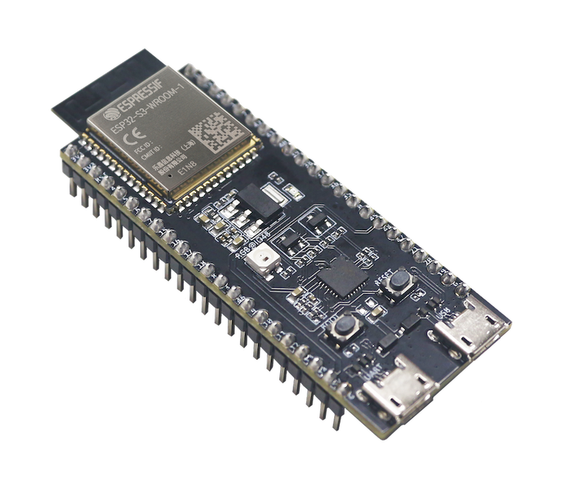
ESP32S3-DevKit
The ESP32S3 DevKit is a development board for the ESP32-S3 SoC from Espressif, based on a ESP32-S3-WROOM-1 module.
|
Features
ESP32-S3-WROOM-1 Module
USB-to-UART bridge via micro USB port
Power LED
EN and BOOT buttons (BOOT accessible to user)
SPI FLASH (size varies according to model
Serial Console
UART0 is, by default, the serial console. It connects to the on-board CP2102 converter and is available on the USB connector USB CON8 (J1).
It will show up as /dev/ttyUSB[n] where [n] will probably be 0.
I2S
ESP32-S3 has two I2S peripherals accessible using either the generic I2S audio driver or a specific audio codec driver (CS4344 bindings are available at the moment). The generic I2S audio driver enables the use of both the receiver module (RX) and the transmitter module (TX) without using any specific codec. Also, it’s possible to use the I2S character device driver to bypass the audio subsystem and write directly to the I2S peripheral.
Configurations
All of the configurations presented below can be tested by running the following commands:
$ ./tools/configure.sh esp32s3-devkit:<config_name>
$ make flash ESPTOOL_PORT=/dev/ttyUSB0 -j
Where <config_name> is the name of board configuration you want to use, i.e.: nsh, buttons, wifi…
Then use a serial console terminal like picocom configured to 115200 8N1.
adc
The adc configuration enables the ADC driver and the ADC example application.
ADC Unit 1 is registered to /dev/adc0 with channels 0, 1, 2 and 3 enabled by default.
Currently, the ADC operates in oneshot mode.
More ADC channels can be enabled or disabled in ADC Configuration menu.
This example shows channels 0 and 1 connected to 3.3 V and channels 2 and 3 to GND (all readings show in units of mV):
nsh> adc -n 1
adc_main: g_adcstate.count: 1
adc_main: Hardware initialized. Opening the ADC device: /dev/adc0
Sample:
1: channel: 0 value: 3061
2: channel: 1 value: 3061
3: channel: 2 value: 106
4: channel: 3 value: 99
audio
This configuration uses the I2S0 peripheral and an externally connected audio codec to play an audio file streamed over an HTTP connection while connected to a Wi-Fi network.
Audio Codec Setup
The CS4344 audio codec is connected to the following pins:
ESP32-S3 Pin |
CS4344 Pin |
Description |
|---|---|---|
5 |
MCLK |
Master Clock |
16 |
SCLK |
Serial Clock |
7 |
LRCK |
Left Right Clock (Word Select) |
6 |
SDIN |
Serial Data In on CS4344. (DOUT on ESP32-S3) |
Simple HTTP server
Prepare a PCM-encoded (.wav) audio file with 16 or 24 bits/sample (sampled at 16~48kHz). This file must be placed into a folder in a computer that could be accessed on the same Wi-Fi network the ESP32 will be connecting to.
Python provides a simple HTTP server. cd to the audio file folder on the
PC and run:
$ python3 -m http.server
Serving HTTP on 0.0.0.0 port 8000 (http://0.0.0.0:8000/)
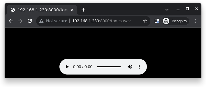
Look for your PC IP address and test playing the prepared audio on your browser:
After successfully built and flashed, connect the board to the Wi-Fi network:
nsh> wapi psk wlan0 mypasswd 3
nsh> wapi essid wlan0 myssid 1
nsh> renew wlan0
Once connected, open NuttX’s player and play the file according to the filename and the IP address of the HTTP server:
nsh> nxplayer
nxplayer> play http://192.168.1.239:8000/tones.wav
capture
The capture configuration enables the capture driver and the capture example, allowing the user to measure duty cycle and frequency of a signal. Default pin is GPIO 12 with an internal pull-up resistor enabled. When connecting a 50 Hz pulse with 50% duty cycle, the following output is expected:
nsh> cap
cap_main: Hardware initialized. Opening the capture device: /dev/capture0
cap_main: Number of samples: 0
pwm duty cycle: 50 %
pwm frequency: 50 Hz
pwm duty cycle: 50 %
pwm frequency: 50 Hz
coremark
This configuration sets the CoreMark benchmark up for running on the maximum number of cores for this system. It also enables some optimization flags and disables the NuttShell to get the best possible score.
Note
As the NSH is disabled, the application will start as soon as the system is turned on.
crypto
This configuration enables support for the cryptographic hardware and
the /dev/crypto device file. Currently, we are supporting SHA-1,
SHA-224 and SHA-256 algorithms using hardware.
To test hardware acceleration, you can use hmac example and following output
should look like this:
nsh> hmac
...
hmac sha1 success
hmac sha1 success
hmac sha1 success
hmac sha256 success
hmac sha256 success
hmac sha256 success
cxx
Development environment ready for C++ applications. You can check if the setup
was successful by running cxxtest:
nsh> cxxtest
Test ofstream ================================
printf: Starting test_ostream
printf: Successfully opened /dev/console
cout: Successfully opened /dev/console
Writing this to /dev/console
Test iostream ================================
Hello, this is only a test
Print an int: 190
Print a char: d
Test std::vector =============================
v1=1 2 3
Hello World Good Luck
Test std::map ================================
Test C++17 features ==========================
File /proc/meminfo exists!
Invalid file! /invalid
File /proc/version exists!
elf
This configuration uses apps/examples/elf in order to test the ELF loader.
It can be tested by executing the elf application.
gpio
This is a test for the GPIO driver. Three GPIOS are defined: 1) GPIO15 is set as an output, 2) GPIO18 as input and, 3) GPIO21 as an input triggered by a rising edge.
This example also builds the EXAMPLES_GPIO application from the
nuttx-apps.
To write to the GPIO (GPIO 15, as defined by the board implementation):
nsh> gpio -o 1 /dev/gpio0
nsh> gpio -o 0 /dev/gpio0
To read from the GPIO (GPIO 18, as defined by the board implementation):
nsh> gpio /dev/gpio1
Driver: /dev/gpio1
  Input pin:     Value=1
Finally, we can use the interrupt pin (GPIO21) to send a signal when the interrupt fires:
nsh> gpio -w 14 /dev/gpio2
Driver: /dev/gpio2
  Interrupt pin: Value=0
  Verify:        Value=1
The pin is configured to trigger an interrupt on the rising edge, so after issuing the above command, connect it to 3.3V.
To use dedicated gpio for controlling multiple gpio pin at the same time or having better response time, you need to enable CONFIG_ESPRESSIF_DEDICATED_GPIO option. Dedicated GPIO is suitable for faster response times required applications like simulate serial/parallel interfaces in a bit-banging way. After this option enabled GPIO4 and GPIO5 pins are ready to used as dedicated GPIO pins as input/output mode. These pins are for example, you can use any pin up to 8 pins for input and 8 pins for output for dedicated gpio. To write and read data from dedicated gpio, you need to use write and read calls.
The following snippet demonstrates how to read/write to dedicated GPIO pins:
int fd; = open("/dev/dedic_gpio0", O_RDWR);
int rd_val = 0;
int wr_mask = 0xffff;
int wr_val = 3;

while(1)
  {
    write(fd, &wr_val, wr_mask);
    if (wr_val == 0)
      {
        wr_val = 3;
      }
    else
      {
        wr_val = 0;
      }
    read(fd, &rd_val, sizeof(uint32_t));
    printf("rd_val: %d", rd_val);
  }
i2c
This configuration can be used to scan and manipulate I2C devices. You can scan for all I2C devices using the following command:
nsh> i2c dev 0x00 0x7f
To use slave mode, you can enable ESP32S3_I2S0_ROLE_SLAVE or ESP32S3_I2S1_ROLE_SLAVE option. To use slave mode driver following snippet demonstrates how write to i2c bus using slave driver:
#define ESP_I2C_SLAVE_PATH  "/dev/i2cslv0"
int main(int argc, char *argv[])
  {
    int i2c_slave_fd;
    int ret;
    uint8_t buffer[5] = {0xAA};
    i2c_slave_fd = open(ESP_I2C_SLAVE_PATH, O_RDWR);
    ret = write(i2c_slave_fd, buffer, 5);
    close(i2c_slave_fd);
 }
i2schar
This configuration enables the I2S character device and the i2schar example app, which provides an easy-to-use way of testing the I2S peripherals (I2S0 and I2S1), enabling both the TX and the RX for those peripherals.
I2S0 pinout
ESP32-S3 Pin |
Signal Pin |
Description |
|---|---|---|
0 |
MCLK |
Master Clock |
4 |
BCLK |
Bit Clock (SCLK) |
5 |
WS |
Word Select (LRCLK) |
18 |
DOUT |
Data Out |
19 |
DIN |
Data IN |
I2S1 pinout
ESP32-S3 Pin |
Signal Pin |
Description |
|---|---|---|
22 |
BCLK |
Bit Clock (SCLK) |
23 |
WS |
Word Select (LRCLK) |
25 |
DOUT |
Data Out |
26 |
DIN |
Data IN |
After successfully built and flashed, run on the boards’s terminal:
i2schar -p /dev/i2schar[0-1]
The corresponding output should show related debug information.
knsh
This is identical to the nsh configuration except that (1) NuttX is built as PROTECTED mode, monolithic module and the user applications are built separately and, as a consequence, (2) some features that are only available in the FLAT build are disabled.
Protected Mode support for ESP32-S3 relies on the World Controller (WC) and Permission Control (PMS) peripherals for implementing isolation between Kernel and Userspace.
By working together with the MMU and Static MPUs of the ESP32-S3, the WC/PMS is able to restrict the application access to peripherals, on-chip memories (Internal ROM and Internal SRAM) and off-chip memories (External Flash and PSRAM).
Warning
The World Controller and Permission Control do not prevent the application from accessing CPU System Registers.
mbedtls
This configuration is to test mbedtls.
A benchmark result:
MD5                      :      13300 KiB/s,          0 cycles/byte
RIPEMD160                :       5658 KiB/s,          0 cycles/byte
SHA-1                    :       6460 KiB/s,          0 cycles/byte
SHA-256                  :       3358 KiB/s,          0 cycles/byte
SHA-512                  :       1519 KiB/s,          0 cycles/byte
SHA3-224                 :        473 KiB/s,          2 cycles/byte
SHA3-256                 :        472 KiB/s,          2 cycles/byte
SHA3-384                 :        382 KiB/s,          2 cycles/byte
SHA3-512                 :        256 KiB/s,          3 cycles/byte
3DES                     :        712 KiB/s,          1 cycles/byte
DES                      :       1743 KiB/s,          0 cycles/byte
3DES-CMAC                :        665 KiB/s,          1 cycles/byte
AES-CBC-128              :       3002 KiB/s,          0 cycles/byte
AES-CBC-192              :       2656 KiB/s,          0 cycles/byte
AES-CBC-256              :       2365 KiB/s,          0 cycles/byte
AES-CFB128-128           :       2815 KiB/s,          0 cycles/byte
AES-CFB128-192           :       2499 KiB/s,          0 cycles/byte
AES-CFB128-256           :       2262 KiB/s,          0 cycles/byte
AES-CFB8-128             :        207 KiB/s,          4 cycles/byte
AES-CFB8-192             :        181 KiB/s,          5 cycles/byte
AES-CFB8-256             :        161 KiB/s,          6 cycles/byte
AES-CTR-128              :       2894 KiB/s,          0 cycles/byte
AES-CTR-192              :       2567 KiB/s,          0 cycles/byte
AES-CTR-256              :       2317 KiB/s,          0 cycles/byte
AES-XTS-128              :       2827 KiB/s,          0 cycles/byte
AES-XTS-256              :       2261 KiB/s,          0 cycles/byte
AES-GCM-128              :        643 KiB/s,          1 cycles/byte
AES-GCM-192              :        627 KiB/s,          1 cycles/byte
AES-GCM-256              :        612 KiB/s,          1 cycles/byte
AES-CCM-128              :       1350 KiB/s,          0 cycles/byte
AES-CCM-192              :       1207 KiB/s,          0 cycles/byte
AES-CCM-256              :       1087 KiB/s,          0 cycles/byte
ChaCha20-Poly1305        :       2093 KiB/s,          0 cycles/byte
AES-CMAC-128             :       2654 KiB/s,          0 cycles/byte
AES-CMAC-192             :       2376 KiB/s,          0 cycles/byte
AES-CMAC-256             :       2134 KiB/s,          0 cycles/byte
AES-CMAC-PRF-128         :       2644 KiB/s,          0 cycles/byte
ARIA-CBC-128             :       1329 KiB/s,          0 cycles/byte
ARIA-CBC-192             :       1140 KiB/s,          0 cycles/byte
ARIA-CBC-256             :       1015 KiB/s,          0 cycles/byte
CAMELLIA-CBC-128         :       1904 KiB/s,          0 cycles/byte
CAMELLIA-CBC-192         :       1515 KiB/s,          0 cycles/byte
CAMELLIA-CBC-256         :       1518 KiB/s,          0 cycles/byte
ChaCha20                 :       2732 KiB/s,          0 cycles/byte
Poly1305                 :      11615 KiB/s,          0 cycles/byte
CTR_DRBG (NOPR)          :       2336 KiB/s,          0 cycles/byte
CTR_DRBG (PR)            :       1607 KiB/s,          0 cycles/byte
HMAC_DRBG SHA-1 (NOPR)   :        441 KiB/s,          2 cycles/byte
HMAC_DRBG SHA-1 (PR)     :        408 KiB/s,          2 cycles/byte
HMAC_DRBG SHA-256 (NOPR) :        339 KiB/s,          2 cycles/byte
HMAC_DRBG SHA-256 (PR)   :        342 KiB/s,          2 cycles/byte
RSA-2048                 :      42  public/s
RSA-2048                 :       2 private/s
RSA-3072                 :      20  public/s
RSA-3072                 :       1 private/s
RSA-4096                 :      11  public/s
RSA-4096                 :       0 private/s
DHE-2048                 :       0 handshake/s
DH-2048                  :       0 handshake/s
DHE-3072                 :       0 handshake/s
DH-3072                  :       0 handshake/s
ECDSA-secp521r1          :       4 sign/s
ECDSA-brainpoolP512r1    :       1 sign/s
ECDSA-secp384r1          :       5 sign/s
ECDSA-brainpoolP384r1    :       1 sign/s
ECDSA-secp256r1          :      11 sign/s
ECDSA-secp256k1          :       9 sign/s
ECDSA-brainpoolP256r1    :       2 sign/s
ECDSA-secp224r1          :      16 sign/s
ECDSA-secp224k1          :      11 sign/s
ECDSA-secp192r1          :      21 sign/s
ECDSA-secp192k1          :      13 sign/s
ECDSA-secp521r1          :       2 verify/s
ECDSA-brainpoolP512r1    :       0 verify/s
ECDSA-secp384r1          :       3 verify/s
ECDSA-brainpoolP384r1    :       1 verify/s
ECDSA-secp256r1          :       6 verify/s
ECDSA-secp256k1          :       5 verify/s
ECDSA-brainpoolP256r1    :       1 verify/s
ECDSA-secp224r1          :       8 verify/s
ECDSA-secp224k1          :       6 verify/s
ECDSA-secp192r1          :      11 verify/s
ECDSA-secp192k1          :       7 verify/s
ECDHE-secp521r1          :       2 ephemeral handshake/s
ECDHE-brainpoolP512r1    :       0 ephemeral handshake/s
ECDHE-secp384r1          :       3 ephemeral handshake/s
ECDHE-brainpoolP384r1    :       1 ephemeral handshake/s
ECDHE-secp256r1          :       6 ephemeral handshake/s
ECDHE-secp256k1          :       5 ephemeral handshake/s
ECDHE-brainpoolP256r1    :       1 ephemeral handshake/s
ECDHE-secp224r1          :       8 ephemeral handshake/s
ECDHE-secp224k1          :       6 ephemeral handshake/s
ECDHE-secp192r1          :      12 ephemeral handshake/s
ECDHE-secp192k1          :       7 ephemeral handshake/s
ECDHE-x25519             :       6 ephemeral handshake/s
ECDHE-x448               :       2 ephemeral handshake/s
ECDH-secp521r1           :       4 static handshake/s
ECDH-brainpoolP512r1     :       1 static handshake/s
ECDH-secp384r1           :       6 static handshake/s
ECDH-brainpoolP384r1     :       1 static handshake/s
ECDH-secp256r1           :      11 static handshake/s
ECDH-secp256k1           :      10 static handshake/s
ECDH-brainpoolP256r1     :       2 static handshake/s
ECDH-secp224r1           :      17 static handshake/s
ECDH-secp224k1           :      11 static handshake/s
ECDH-secp192r1           :      23 static handshake/s
ECDH-secp192k1           :      14 static handshake/s
ECDH-x25519              :      12 static handshake/s
ECDH-x448                :       5 static handshake/s
motor
The motor configuration enables the MCPWM peripheral with support to brushed DC motor control.
It creates a /dev/motor0 device with speed and direction control capabilities
by using two GPIOs (GPIO15 and GPIO16) for PWM output. PWM frequency is configurable
from 25 Hz to 3 kHz, however it defaults to 1 kHz.
There is also support for an optional fault GPIO (defaults to GPIO10), which can be used
for quick motor braking. All GPIOs are configurable in menuconfig.
mcuboot_nsh
This configuration is the same as the nsh configuration, but it generates the application
image in a format that can be used by MCUboot. It also makes the make bootloader command to
build the MCUboot bootloader image using the Espressif HAL.
mcuboot_update_agent
This configuration is used to represent an MCUboot image that contains an update agent to perform over-the-air (OTA) updates. Wi-Fi settings are already enabled and image confirmation program is included.
Follow the instructions in the MCUBoot and OTA Update section to execute OTA update.
nsh
Basic NuttShell configuration (console enabled in UART0, exposed via USB connection by means of CP2102 converter, at 115200 bps).
nxlooper
This configuration uses the I2S1 peripheral as an I2S receiver and the I2S0 peripheral as an I2S transmitter. The idea is to capture an I2S data frame using an I2S peripheral and reproduce the captured data on the other.
Receiving data on I2S1
The I2S1 will act as a receiver (in slave mode, i.e., waiting for the BCLK and WS signals from the transmitter), capturing data from DIN, which needs to be connected to an external source as follows:
ESP32-S3 Pin |
Signal Pin |
Description |
|---|---|---|
18 |
BCLK |
Bit Clock (SCLK) |
17 |
WS |
Word Select (LRCLK) |
15 |
DIN |
Data IN |
Transmitting data on I2S0
The I2S0 will act as a transmitter (in master mode, i.e., providing the BCLK and WS signals), replicating the data captured on I2S1. The pinout for the transmitter is as follows:
ESP32 Pin |
Signal Pin |
Description |
|---|---|---|
5 |
MCLK |
Master Clock |
16 |
BCLK |
Bit Clock (SCLK) |
7 |
WS |
Word Select (LRCLK) |
6 |
DOUT |
Data Out |
Note
The audio codec CS4344 can be connected to the transmitter pins to reproduce the captured data if the receiver’s source is a PCM-encoded audio data.
nxlooper
The nxlooper application captures data from the audio device with input
capabilities (the I2S1 in this example) and forwards the audio data frame to
the audio device with output capabilities (the I2S0 in this example).
After successfully built and flashed, run on the boards’ terminal:
nsh> nxlooper
nxlooper> loopback
Note
loopback command default arguments for the channel configuration,
data width and sample rate are, respectively, 2 channels,
16 bits/sample and 48KHz. These arguments can be supplied to select
different audio formats, for instance:
nxlooper> loopback 2 16 44100
oneshot
This config demonstrate the use of oneshot timers present on the ESP32-S3.
To test it, just run the oneshot example:
nsh> oneshot
Opening /dev/oneshot
Maximum delay is 4294967295999999
Starting oneshot timer with delay 2000000 microseconds
Waiting...
Finished
ostest
This is the NuttX test at apps/testing/ostest that is run against all new architecture ports to assure a correct implementation of the OS.
qencoder —
This configuration demonstrates the use of Quadrature Encoder connected to pins
GPIO10 and GPIO11. You can start measurement of pulses using the following
command (by default, it will open \dev\qe0 device and print 20 samples
using 1 second delay):
nsh> qe
pm
This config demonstrate the use of power management present on the ESP32-S3.
You can use the pmconfig command to test the power management.
Enables PM support. You can define standby mode and sleep mode delay time:
$ make menuconfig
-> Board Selection
    -> (15) PM_STANDBY delay (seconds)
       (0)  PM_STANDBY delay (nanoseconds)
       (20) PM_SLEEP delay (seconds)
       (0)  PM_SLEEP delay (nanoseconds)
You can also define an EXT1 wakeup for both sleep modes by selecting which RTC GPIO will be used and the logic level that will trigger it:
$ make menuconfig
-> Board Selection
    -> [*] PM EXT1 Wakeup
              PM EXT1 Wakeup Sources  --->
                [ ] RTC_GPIO<N>
          (0) PM EXT1 Wakeup Trigger Mode
To enable ULP coprocessor wakeup CONFIG_PM_ULP_WAKEUP option needs to be enabled.
After that, ULP core can wake up HP core using ulp_riscv_wakeup_main_processor function
which needs to be called in the ULP app.
Before switching PM status, you need to query the current PM status:
nsh> pmconfig
Last state 0, Next state 0

/proc/pm/state0:
DOMAIN0           WAKE         SLEEP         TOTAL
normal          0s 00%        0s 00%        0s 00%
idle            0s 00%        0s 00%        0s 00%
standby         0s 00%        0s 00%        0s 00%
sleep           0s 00%        0s 00%        0s 00%

/proc/pm/wakelock0:
DOMAIN0      STATE     COUNT      TIME
system       normal        2        1s
system       idle          1        1s
system       standby       1        1s
system       sleep         1        1s
System switch to the PM idle mode, you need to enter:
nsh> pmconfig relax normal
nsh> pmconfig relax normal
System switch to the PM standby mode, you need to enter:
nsh> pmconfig relax idle
nsh> pmconfig relax normal
nsh> pmconfig relax normal
System switch to the PM sleep mode, you need to enter:
nsh> pmconfig relax standby
nsh> pmconfig relax idle
nsh> pmconfig relax normal
nsh> pmconfig relax normal
Note: When normal mode COUNT is 0, it will switch to the next PM state where COUNT is not 0.
psram_quad
This config tests the PSRAM driver over SPIRAM interface in quad mode. You can use the mm command to test the PSRAM memory:
nsh> mm
    mallinfo:
      Total space allocated from system = 8803232
      Number of non-inuse chunks        = 2
      Largest non-inuse chunk           = 8388592
      Total allocated space             = 9672
      Total non-inuse space             = 8793560
(0)Allocating 5011 bytes

......

(31)Releasing memory at 0x3fc8c088 (size=24 bytes)
    mallinfo:
      Total space allocated from system = 8803232
      Number of non-inuse chunks        = 2
      Largest non-inuse chunk           = 8388592
      Total allocated space             = 9672
      Total non-inuse space             = 8793560
TEST COMPLETE
psram_octal
Similar to the `psram_quad` configuration but using the SPIRAM
interface in octal mode.
psram_usrheap
This configuration enables allocating the userspace heap into SPI RAM and reserves the internal RAM for kernel heap.
Important: this config defaults to flash QUAD mode, and should be changed if the board
runs on OCTAL mode by setting CONFIG_ESP32S3_SPIRAM_MODE_OCT. If wrong, a SPIRAM error
will appear during boot.
To check the flash type, run the following command:
$ esptool.py flash_id
esptool.py v4.8.1
Found 33 serial ports
Serial port /dev/ttyUSB0
Connecting....
Detecting chip type... ESP32-S3
Chip is ESP32-S3 (QFN56) (revision v0.1)
Features: WiFi, BLE, Embedded PSRAM 2MB (AP_3v3)
Crystal is 40MHz
MAC: 7c:df:a1:e5:d8:5c
Uploading stub...
Running stub...
Stub running...
Manufacturer: 20
Device: 4017
Detected flash size: 8MB
Flash type set in eFuse: quad (4 data lines)
Flash voltage set by eFuse to 3.3V
Hard resetting via RTS pin...
The flash type can be seen on the “Flash type set in eFuse: quad” line.
pwm
This configuration demonstrates the use of PWM through a LED connected to GPIO2.
To test it, just execute the pwm application:
nsh> pwm
pwm_main: starting output with frequency: 10000 duty: 00008000
pwm_main: stopping output
python
This configuration enables the Python for ESP32-S3. Please refer to the Python Interpreter page.
Warning
Note that this defconfig uses a board with the ESP32-S3-WROOM-2 module with 32MiB of flash and 8MiB of PSRAM. Running Python on ESP32-S3 requires at least 16MiB of flash and 8MiB of PSRAM.
qemu_debug
A configuration tailored for the Espressif fork of QEMU.
qemu_toywasm
Based on qemu_debug defconfig, with the addition of WebAssembly support.
See toywasm for more further details.
random
This configuration shows the use of the ESP32-S3’s True Random Number Generator with
entropy sourced from Wi-Fi and Bluetooth noise.
To test it, just run rand to get 32 randomly generated bytes:
nsh> rand
Reading 8 random numbers
Random values (0x3ffe0b00):
0000  98 b9 66 a2 a2 c0 a2 ae 09 70 93 d1 b5 91 86 c8  ..f......p......
0010  8f 0e 0b 04 29 64 21 72 01 92 7c a2 27 60 6f 90  ....)d!r..|.'`o.
rmt
This configuration configures the transmitter and the receiver of the
Remote Control Transceiver (RMT) peripheral on the ESP32-S3 using GPIOs 48
(or 38, depending on the board version) and 2, respectively.
The RMT peripheral is better explained
here,
in the ESP-IDF documentation. The minimal data unit in the frame is called the
RMT symbol, which is represented by rmt_item32_t in the driver:

The example irtest can be used to test the RMT peripheral. Connecting
these pins externally to each other will make the transmitter send RMT items
and demonstrates the usage of the RMT peripheral:
nsh> irtest
$open_device(/dev/lirc0)
$open_device(/dev/lirc1)
$write_data(1) 16777229 16 16777235 23
$read_data(0,4)
16777229, 16, 16777235, 23
WS2812 addressable RGB LEDs
This same configuration enables the usage of the RMT peripheral and the example
ws2812 to drive addressable RGB LEDs:
nsh> ws2812
Please note that this board contains an on-board WS2812 LED connected to GPIO48 (or GPIO38, depending on the board version) and, by default, this config configures the RMT transmitter in the same pin.
romfs
This configuration demonstrates the use of ROMFS (Read-Only Memory File System) to provide
automated system initialization and startup scripts. ROMFS allows embedding a read-only
filesystem directly into the NuttX binary, which is mounted at /etc during system startup.
What ROMFS provides:
System initialization script (
/etc/init.d/rc.sysinit): Executed after board bring-upStartup script (
/etc/init.d/rcS): Executed after system init, typically used to start applications
Default behavior:
When this configuration is used, NuttX will:
Create a read-only RAM disk containing the ROMFS filesystem
Mount the ROMFS at
/etcExecute
/etc/init.d/rc.sysinitduring system initializationExecute
/etc/init.d/rcSfor application startup
Customizing startup scripts:
The startup scripts are located in:
boards/xtensa/esp32s3/common/src/etc/init.d/
rc.sysinit- System initialization scriptrcS- Application startup script
To customize these scripts:
Edit the script files in
boards/xtensa/esp32s3/common/src/etc/init.d/Add your initialization commands using any NSH-compatible commands
Example customizations:
rc.sysinit - Set up system services, mount additional filesystems, configure network.
rcS - Start your application, launch daemons, configure peripherals. This is executed after the rc.sysinit script.
Example output:
*** Booting NuttX ***
[...]
rc.sysinit is called!
rcS file is called!
NuttShell (NSH) NuttX-12.8.0
nsh> ls /etc/init.d
/etc/init.d:
.
..
rc.sysinit
rcS
rtc
This configuration demonstrates the use of the RTC driver through alarms. You can set an alarm, check its progress and receive a notification after it expires:
nsh> alarm 10
alarm_daemon started
alarm_daemon: Running
Opening /dev/rtc0
Alarm 0 set in 10 seconds
nsh> alarm -r
Opening /dev/rtc0
Alarm 0 is active with 10 seconds to expiration
nsh> alarm_daemon: alarm 0 received
sdm
This configuration enables the support for the Sigma-Delta Modulation (SDM) driver which can be used for LED dimming, simple dac with help of an low pass filter either active or passive and so on. ESP32-S3 supports 1 group of SDM up to 8 channels with any GPIO up to user. This configuration enables 1 channel of SDM on GPIO5. You can test DAC feature with following command with connecting simple LED on GPIO5
nsh> dac -d 100 -s 10 test
After this command you will see LED will light up in different brightness.
sdmmc
Based on nsh. Support for sdmmc driver is enabled with following settings:
Enable sdmmc driver:
CONFIG_ESP32S3_SDMMC=y
Default GPIO definitions:
CONFIG_ESP32S3_SDMMC_CMD=41
CONFIG_ESP32S3_SDMMC_CLK=39
CONFIG_ESP32S3_SDMMC_D0=40
CONFIG_ESP32S3_SDMMC_D1=16
CONFIG_ESP32S3_SDMMC_D2=8
CONFIG_ESP32S3_SDMMC_D3=42
Multiblock limitation due to hardware:
CONFIG_MMCSD_MULTIBLOCK_LIMIT=128
Use sched_yield instead of usleep due to long tick time:
CONFIG_MMCSD_CHECK_READY_STATUS_WITHOUT_SLEEP=y
This configuration has been verified with an adapter (1.27 to 2.54mm T-type adapter, CN10P2) and an external emmc module.
Besides the connections to 3v3 and GND of ESP32S3 DevKit, pins of the adapter used in the verification are connected to ESP32S3 DevKit as following:
adapter pin           ESP32S3 GPIO
    11      ===CMD==>       41
    12      ===CLK==>       39
    1       ===D0===>       40
    2       ===D1===>       16
    3       ===D2===>       8
    4       ===D3===>       42
Format and mount the SD/MMC device with following commands:
mkfatfs -F 32 -r /mnt /dev/mmcsd1
mount -t vfat /dev/mmcsd1 /mnt
FAT filesystem is enabled in the default configuration. Other filesystems may also work.
sdmmc_spi
This configuration is used to mount a FAT/FAT32 SD Card into the OS’ filesystem. It uses SPI to communicate with the SD Card, defaulting to SPI2.
The SD slot number, SPI port number and minor number can be modified in Application Configuration → NSH Library.
To access the card’s files, make sure /dev/mmcsd0 exists and then execute the following commands:
nsh> ls /dev
/dev:
console
mmcsd0
null
ttyS0
zero
nsh> mount -t vfat /dev/mmcsd0 /mnt
This will mount the SD Card to /mnt. Now, you can use the SD Card as a normal filesystem.
For example, you can read a file and write to it:
nsh> ls /mnt
/mnt:
hello.txt
nsh> cat /mnt/hello.txt
Hello World
nsh> echo 'NuttX RTOS' >> /mnt/hello.txt
nsh> cat /mnt/hello.txt
Hello World!
NuttX RTOS
nsh>
smp
Another NSH configuration, similar to nsh, but also enables SMP operation. It differs from the nsh configuration only in these additional settings:
SMP is enabled:
CONFIG_SMP=y
CONFIG_SMP_NCPUS=2
CONFIG_SPINLOCK=y
The apps/testing/smp test is included:
CONFIG_TESTING_SMP=y
CONFIG_TESTING_SMP_NBARRIER_THREADS=8
CONFIG_TESTING_SMP_PRIORITY=100
CONFIG_TESTING_SMP_STACKSIZE=2048
spiflash
This config tests the external SPI that comes with the ESP32-S3 module connected through SPI1.
By default a SmartFS file system is selected. Once booted you can use the following commands to mount the file system:
nsh> mksmartfs /dev/smart0
nsh> mount -t smartfs /dev/smart0 /mnt
Note that mksmartfs is only needed the first time.
spislv
This configuration enables the SPI2 peripheral in slave mode and
provides the spislv example application to test data exchange with an
external SPI master.
After building and flashing the firmware, run the following command on the board terminal:
nsh> spislv -x 5 1a2b3c4d5e
This command enqueues the data sequence 1a2b3c4d5e in the slave buffer.
On the next transfer, the external SPI master should receive this data back
from the slave.
By default, SPI2 pins are used for the slave interface. The exact pin mapping
depends on the ESP32-S3 DevKit version and can be adjusted through
menuconfig under System type → SPI configuration.
sta_softap
With this configuration you can run these commands to be able to connect your smartphone or laptop to your board:
nsh> ifup wlan1
nsh> dhcpd_start wlan1
nsh> wapi psk wlan1 mypasswd 3
nsh> wapi essid wlan1 nuttxap 1
In this case, you are creating the access point nuttxapp in your board and to
connect to it on your smartphone you will be required to type the password mypasswd
using WPA2.
Tip
Please refer to ESP32 Wi-Fi SoftAP Mode for more information.
The dhcpd_start is necessary to let your board to associate an IP to your smartphone.
tickless
This configuration enables the support for tickless scheduler mode.
timer
This config test the general use purpose timers. It includes the 4 timers, adds driver support, registers the timers as devices and includes the timer example.
To test it, just run the following:
nsh> timer -d /dev/timerx
Where x in the timer instance.
toywasm
This config is an example to use toywasm.
This example uses littlefs on the SPI flash to store wasm modules.
Note: This example assumes a board with 32MB flash. To use a smaller one, tweak the –img-size option and CONFIG_ESP32S3_STORAGE_MTD_SIZE.
Note: To use flash larger than 4MB, you need to install a custom bootloader. https://docs.espressif.com/projects/esp-idf/en/stable/esp32/api-guides/bootloader.html#spi-flash-configuration
Create a littlefs image which contains wasm modules.
https://github.com/jrast/littlefs-python/blob/master/examples/mkfsimg.py is used in the following example:
% python3 mkfsimg.py \
  --img-filename ..../littlefs.bin \
  --img-size 31981568 \
  --block-size 4096 \
  --prog-size 256 \
  --read-size 256 \
  --name-max 32 \
  --disk-version 2.0 \
  ..../wasm_module_dir
Build a NuttX binary and write it to the board as usual with this config.
Write the filesystem image to the board:
% esptool.py \
  -c esp32s3 \
  -p /dev/tty.SLAB_USBtoUART \
  -b 921600 \
  write_flash \
  -fs detect \
  -fm dio \
  -ff 40m \
  0x180000 ..../littlefs.bin
Mount the filesystem and run a wasm module on it:
nsh> mount -t littlefs /dev/esp32s3flash /mnt
nsh> toywasm --print-stats --wasi /mnt/....
twai
This configuration enables the support for the TWAI (Two-Wire Automotive Interface) driver.
You can test it by connecting TWAI RX and TWAI TX pins which are GPIO0 and GPIO2 by default
to a external transceiver or connecting TWAI RX to TWAI TX pin by enabling
the Device Drivers -> CAN Driver Support -> CAN loopback mode option and running the can example:
nsh> can
nmsgs: 0
min ID: 1 max ID: 2047
Bit timing:
  Baud: 1000000
  TSEG1: 15
  TSEG2: 4
    SJW: 3
  ID:    1 DLC: 1
ulp
This configuration enables the support for the ULP RISC-V core coprocessor. To get more information about LP Core please check ULP LP Core Coprocessor docs.
Configuration uses a pre-built binary in Documentation/platforms/xtensa/esp32s3/boards/esp32s3-devkit/ulp_riscv_blink.bin
which is a blink example for GPIO0. After flashing operation, GPIO0 pin will blink.
Prebuild binary runs this code:
#include <stdio.h>
#include <stdint.h>
#include <stdbool.h>
#include "ulp_riscv.h"
#include "ulp_riscv_utils.h"
#include "ulp_riscv_gpio.h"

#define GPIO_PIN 0

#define nop() __asm__ __volatile__ ("nop")

bool gpio_level_previous = true;

int main (void)
 {
    while (1)
        {
        ulp_riscv_gpio_output_level(GPIO_PIN, gpio_level_previous);
        gpio_level_previous = !gpio_level_previous;
        for (int i = 0; i < 10000; i++)
          {
            nop();
          }
        }

    return 0;
 }
usbnsh
Basic NuttShell configuration console enabled over USB Device (USB CDC/ACM).
Before using this configuration, please confirm that your computer detected that USB JTAG/serial interface used to flash the board:
usb 3-5.2.3: New USB device strings: Mfr=1, Product=2, SerialNumber=3
usb 3-5.2.3: Product: USB JTAG/serial debug unit
usb 3-5.2.3: Manufacturer: Espressif
usb 3-5.2.3: SerialNumber: XX:XX:XX:XX:XX:XX
cdc_acm 3-5.2.3:1.0: ttyACM0: USB ACM device
Then you can run the configuration and compilation procedure:
$ ./tools/configure.sh esp32s3-devkit:usbnsh
$ make flash ESPTOOL_PORT=/dev/ttyACM0 -j8
Then run the minicom configured to /dev/ttyACM0 115200 8n1 and press <ENTER> three times to force the nsh to show up:
NuttShell (NSH) NuttX-12.1.0
nsh> ?
help usage:  help [-v] [<cmd>]

    .         break     dd        exit      ls        ps        source    umount
    [         cat       df        false     mkdir     pwd       test      unset
    ?         cd        dmesg     free      mkrd      rm        time      uptime
    alias     cp        echo      help      mount     rmdir     true      usleep
    unalias   cmp       env       hexdump   mv        set       truncate  xd
    basename  dirname   exec      kill      printf    sleep     uname

Builtin Apps:
    nsh  sh
nsh> uname -a
NuttX 12.1.0 38a73cd970 Jun 18 2023 16:58:46 xtensa esp32s3-devkit
nsh>
wifi
Enables Wi-Fi support. You can define your credentials this way:
$ make menuconfig
-> Application Configuration
    -> Network Utilities
        -> Network initialization (NETUTILS_NETINIT [=y])
            -> WAPI Configuration
Or if you don’t want to keep it saved in the firmware you can do it at runtime:
nsh> wapi psk wlan0 mypasswd 3
nsh> wapi essid wlan0 myssid 1
nsh> renew wlan0
Tip
Please refer to ESP32 Wi-Fi Station Mode for more information.
watchdog
This config test the watchdog timers. It includes the 2 MWDTS, adds driver support, registers the WDTs as devices and includes the watchdog example.
To test it, just run the following:
nsh> wdog -i /dev/watchdogx
Where x is the watchdog instance.
To test the XTWDT(/dev/watchdog3) an interrupt handler needs to be implemented because XTWDT does not have system reset feature. To implement an interrupt handler WDIOC_CAPTURE command can be used. When interrupt rises, XTAL32K clock can be restored with WDIOC_RSTCLK command.
adb
Basic NuttShell configuration console enabled over USB Device (USB ADB).
You can run the configuration and compilation procedure:
$ ./tools/configure.sh esp32s3-devkit:adb
$ make -j16
$ make flash ESPTOOL_PORT=/dev/ttyACMx
Then run the adb command:
$ adb -s 1234 shell
nsh> uname -a
NuttX 0.0.0  Nov 22 2024 11:41:43 xtensa esp32s3-devkit
txtable
Basic TXTABLE(Text based Partition Table) configuration console enabled over USB ADB.
You can run the configuration and compilation procedure:
$ ./tools/configure.sh -l esp32s3-devkit:txtable
$ make -j16
$ make flash ESPTOOL_PORT=/dev/ttyACMx
Then check the partition:
nsh> ls -l /dev/
/dev:
 dr--r--r--           0 adb0/
 crw-rw-rw-           0 console
 frw-rw-rw-     1044480 data
 frw-rw-rw-     1048576 esp32s3flash
 c-w--w--w-           0 log
 crw-rw-rw-           0 null
 crw-rw-rw-           0 ptmx
 dr--r--r--           0 pts/
 brw-rw-rw-        1024 ram0
 crw-rw-rw-           0 ttyS0
 frw-rw-rw-        4096 txtable
 crw-rw-rw-           0 zero
usbmsc
Basic USBMSC(USB Mass Storage Class) configuration based on esp32s3-devkit:usb_device
You can run the configuration and compilation procedure:
$ ./tools/configure.sh -l esp32s3-devkit:usbmsc
$ make flash ESPTOOL_PORT=/dev/ttyACMx -j16
To test it, just run the following:
# Device
nsh> mkrd -m 10 -s 512 640
nsh> msconn

# Host
$ sudo mkfs.ext4 /dev/sdx
$ sudo mount /dev/sdx ./mnt/
fastboot
You can run the configuration and compilation procedure:
$ ./tools/configure.sh -l esp32s3-devkit:fastboot
$ make flash ESPTOOL_PORT=/dev/ttyACMx -j
To test it, just run the following (Default is host side):
Install fastboot tool:
sudo apt install fastboot
Specify a device / List devices:
List devices only supported for USB transport:
fastboot devices

# Examples

$ fastboot devices
1234    fastboot
To specific a device, use “-s” option:
# Usage
#
#   -s tcp:HOST[:PORT]         Specify a TCP network device.
#   -s SERIAL                  Specify a USB device.

fastboot -s SERIAL COMMAND
fastboot -s tcp:HOST[:PORT] COMMAND

# Examples

$ fastboot -s 1234 oem shell ifconfig
wlan0   Link encap:Ethernet HWaddr a0:85:e3:f4:43:30 at RUNNING mtu 1500
        inet addr:192.168.211.111 DRaddr:192.168.211.107 Mask:255.255.255.0

PS C:\workspace> fastboot.exe -s tcp:192.168.211.111 oem shell ifconfig
wlan0   Link encap:Ethernet HWaddr a0:85:e3:f4:43:30 at RUNNING mtu 1500
        inet addr:192.168.211.111 DRaddr:192.168.211.107 Mask:255.255.255.0
Display given variable:
fastboot getvar <NAME>
Example:
# Display the "kernel" variable::
$ fastboot -s 1234 getvar kernel
Kernel: NuttX
Finished. Total time: 0.000s
Flash given partition:
fastboot flash PARTITION FILENAME
Example (Flash test.img to partition ram10):
# 1. Generate a test image
$ dd if=/dev/random of=test.img bs=1 count=128

# 2. Create a RAM disk (Device side)
nsh> mkrd -m 10 -s 512 640
nsh> ls -l /dev/ram10
 brw-rw-rw-      327680 /dev/ram10

# 3. Flash test.img to partition ram10
$ fastboot flash ram10 ./test.img
Sending 'ram10' (0 KB)                             OKAY [  0.001s]
Writing 'ram10'                                    OKAY [  0.001s]
Finished. Total time: 0.003s

# 4. Hexdump the test.img and partition ram10, and compare

## Host side
$ hexdump test.img
0000000 b1e8 b297 4ac5 9dfa d170 244e 4f83 0f93
0000010 1bf7 0b19 7bde 5543 0520 9719 746d 54fc
0000020 369d 72b3 f2e6 f463 c8e9 24c8 c876 e820
0000030 384d 07ab 52ca 2b24 dee7 0404 2663 91e4
0000040 6752 3611 aece b543 5194 2224 d1d5 8144
0000050 ff44 3bc9 5155 b393 1efb 9e88 2de9 3669
0000060 d010 2770 9192 2532 ccf5 591f 39ea 2431
0000070 2e3f feb0 87ef 9bdf 7dd4 2e79 64de edf6
0000080

## Device side
nsh> hexdump /dev/ram10 count=128
/dev/ram10 at 00000000:
0000: e8 b1 97 b2 c5 4a fa 9d 70 d1 4e 24 83 4f 93 0f .....J..p.N$.O..
0010: f7 1b 19 0b de 7b 43 55 20 05 19 97 6d 74 fc 54 .....{CU ...mt.T
0020: 9d 36 b3 72 e6 f2 63 f4 e9 c8 c8 24 76 c8 20 e8 .6.r..c....$v. .
0030: 4d 38 ab 07 ca 52 24 2b e7 de 04 04 63 26 e4 91 M8...R$+....c&..
0040: 52 67 11 36 ce ae 43 b5 94 51 24 22 d5 d1 44 81 Rg.6..C..Q$"..D.
0050: 44 ff c9 3b 55 51 93 b3 fb 1e 88 9e e9 2d 69 36 D..;UQ.......-i6
0060: 10 d0 70 27 92 91 32 25 f5 cc 1f 59 ea 39 31 24 ..p'..2%...Y.91$
0070: 3f 2e b0 fe ef 87 df 9b d4 7d 79 2e de 64 f6 ed ?........}y..d..
fastboot_usb
You can run the configuration and compilation procedure:
$ ./tools/configure.sh -l lckfb-szpi-esp32s3:fastboot_usb
$ make flash ESPTOOL_PORT=/dev/ttyACMx -j
fastboot_tcp
You can run the configuration and compilation procedure:
$ ./tools/configure.sh -l esp32s3-devkit:fastboot_tcp
$ make flash ESPTOOL_PORT=/dev/ttyACMx -j
To test it, just run the following:
# Device side

nsh> wapi psk wlan0 mypasswd 3
nsh> wapi essid wlan0 myssid 1
nsh> renew wlan0

# Host side

PS C:\workspace> fastboot.exe -s tcp:HOST[:PORT] oem shell ls
/:
 data/
 dev/
 etc/
 proc/
 var/
OKAY [  0.063s]
Finished. Total time: 0.064s