ST STM32N6570-DK
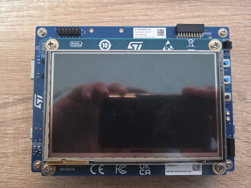
STM32N6570-DK Front
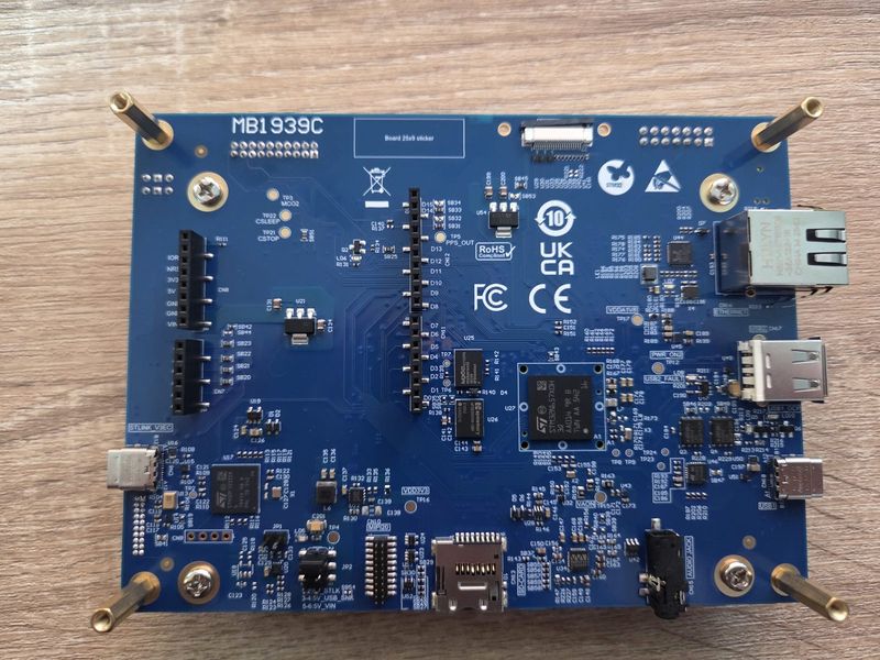
STM32N6570-DK Back
The STM32N6570-DK Discovery kit is based on the STM32N657X0H3Q Arm Cortex-M55 microcontroller.
Loading and running
Use SRAM loading for routine debugging and external flash for persistent boot, reset testing and standalone operation. The console is the ST-LINK Virtual COM Port at 115200 8N1.
Persistent flash
OpenOCD adds the STM32N6 ROM header to nuttx.bin and programs the
on-board NOR flash with its stmqspi driver. Use an OpenOCD version
that provides target/stm32n6x.cfg.
Build and program the persistent boot image with:
$ make flash
This erases the affected flash sectors, programs and verifies the image,
and resets the board. OPENOCD and OPENOCD_TARGET can override the
OpenOCD executable and target script. The board’s scripts/flash.cfg
configures the NOR pins, clocks and geometry for the native flash driver.
For a CMake build configured in build:
$ cmake --build build --target flash
Both targets build nuttx.bin before flashing. With CMake, OPENOCD
and OPENOCD_TARGET are cache variables set with -D at configuration.
The boot ROM loads NuttX from flash and starts it without a debugger or
separate FSBL.
The header and padding occupy the first 1 KiB at 0x34180000; NuttX is
linked at 0x34180400. The ROM download buffer limits the binary to
511 KiB. The generated image is unauthenticated and requires a device
that permits unauthenticated boot.
SRAM debugging
Build with make or cmake --build build. Start OpenOCD using its
standard ST-LINK and STM32N6 scripts:
$ openocd -f interface/stlink.cfg -c 'transport select swd' \
      -f target/stm32n6x.cfg -c 'reset_config srst_only srst_nogate'
In another terminal, open the ELF with GDB. Use build/nuttx instead of
nuttx for CMake:
$ arm-none-eabi-gdb nuttx
(gdb) target extended-remote :3333
(gdb) monitor reset halt
(gdb) load
(gdb) set $msp = *(unsigned int *)0x34180400
(gdb) set $pc = *(unsigned int *)0x34180404
(gdb) hbreak nx_start
(gdb) continue
load writes the ELF sections into SRAM without programming external
flash. The next two commands initialize the stack pointer and entry point
from the vector table. Continue again after reaching nx_start to run
NSH. Reset before each reload; resetting after load boots the image
stored in flash instead. The SRAM image is lost on power-off.
To inspect an already running image, attach with its matching ELF and omit the reset, load and register-setting commands.
NSH enables CONFIG_STM32N6_DEBUG to reopen debug access after ROM boot
and includes debug symbols. These debugging steps require an installed
image that enables debug access. Stop GDB and OpenOCD before running either
flash target.
RTC
The RTC runs from the 32.768 kHz LSE crystal and is registered as
/dev/rtc0 with two alarms. Set the time with date -s and test the
alarms with the alarm example, e.g. alarm 5 or alarm -a 1 5.
The time survives a reset; without a backup battery it is lost on power
off.
I2C
Bus |
Pins |
Devices |
|---|---|---|
I2C1 |
PH9, PC1 |
Camera module connector, Arduino D15/D14 |
I2C2 |
PD14, PD4 |
WM8904 codec (0x1a), GT911 touch (0x5d), TCPP03 |
I2C4 |
PE13, PE14 |
STMod+ connector |
The buses are registered as /dev/i2c1, /dev/i2c2 and /dev/i2c4
and can be explored with the i2c tool.
Serial ports
Port |
Device |
Pins |
Connection |
|---|---|---|---|
USART1 |
ttyS0 |
PE5 TX, PE6 RX |
ST-LINK VCP, console |
USART2 |
ttyS1 |
PD5 TX, PF6 RX, PG5 CTS, PG14 RTS |
STMod+ connector |
Clocking
By default the CPU runs at 800 MHz and the system buses at 400 MHz. PLL1 is fed from the 48 MHz HSE crystal, HCLK and the APB clocks run at 200 MHz and the timer kernel clock is 200 MHz. 800 MHz requires the VOS high voltage range, so the board SMPS is switched to its overdrive output through PF4 before the PLL is started. PLL2, PLL3 and PLL4 are started for the peripheral kernel clocks.
CONFIG_STM32N6570_DK_CLOCK_HSI selects a conservative tree instead: PLL1
from the internal 64 MHz HSI, CPU 200 MHz, SYSCLK 100 MHz and VOS low. The
console USART1 is clocked from HSI in both cases.
Configurations
nsh
NuttShell with the user LEDs, the USER1 button, GPDMA1 and the RTC enabled.