ESP32-S2-Kaluga-1 Kit v1.3
The ESP32-S2-Kaluga-1 kit v1.3 is a development kit by Espressif that is mainly created to:
Demonstrate the ESP32-S2’s human-computer interaction functionalities
Provide the users with the tools for development of human-computer interaction applications based on the ESP32-S2
There are many ways of how the ESP32-S2’s abundant functionalities can be used. For starters, the possible use cases may include:
Smart home: From simplest smart lighting, smart door locks, smart sockets, to video streaming devices, security cameras, OTT devices, and home appliances
Battery-powered equipment: Wi-Fi mesh sensor networks, Wi-Fi-networked toys, wearable devices, health management equipment
Industrial automation equipment: Wireless control and robot technology, intelligent lighting, HVAC control equipment, etc.
Retail and catering industry: POS machines and service robots
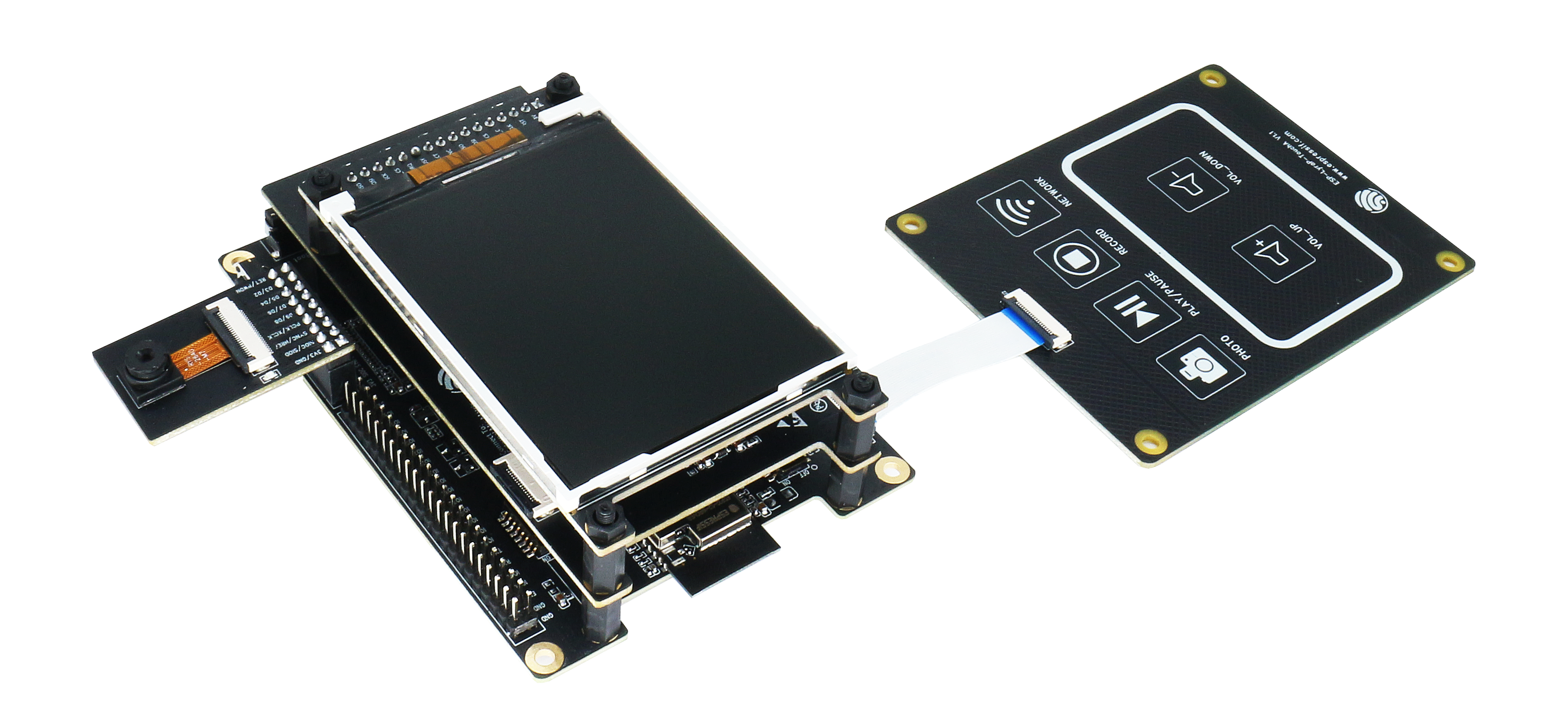
ESP32-S2-Kaluga-1-Kit Overview (click to enlarge)
The ESP32-S2-Kaluga-1 kit consists of the following boards:
Main board: ESP32-S2-Kaluga-1
Extension boards:
ESP-LyraT-8311A - Audio player
ESP-LyraP-TouchA - Touch buttons
ESP-LyraP-LCD32 - 3.2” LCD screen
ESP-LyraP-CAM - Camera module
A block diagram below shows the components of the ESP32-S2-Kaluga-1 and their interconnections.
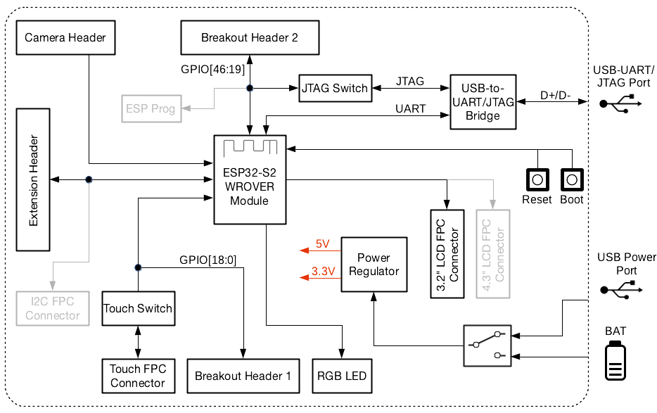
ESP32-S2-Kaluga-1 block diagram
Features
The ESP32-S2-Kaluga-1 main board is the heart of the kit. It integrates the ESP32-S2-WROVER module and all the connectors for extension boards. This board is the key tool in prototyping human-computer interaction interfaces.
The ESP32-S2-Kaluga-1 board has connectors for boards with:
Extension header (ESP-LyraT-8311A, ESP-LyraP-LCD32)
Camera header (ESP-LyraP-CAM)
Touch FPC connector (ESP-LyraP-TouchA)
LCD FPC connector (no official extension boards yet)
I2C FPC connector (no official extension boards yet)
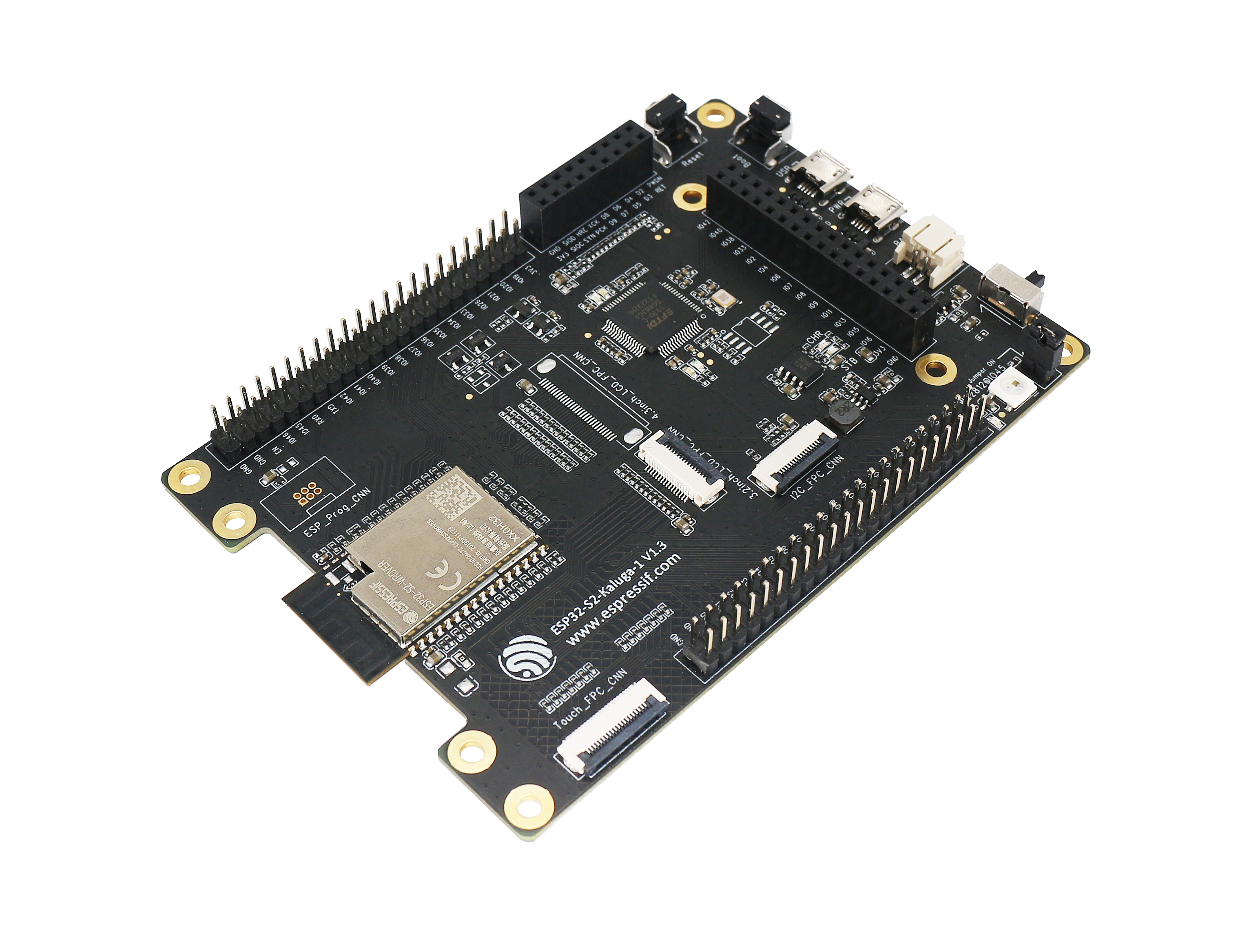
ESP32-S2-Kaluga-1 (click to enlarge)
All the four extension boards are specially designed to support the following features:
- Touch panel control
Six touch buttons
Supports acrylic panels up to 5 mm
Wet hand operation
Water rejection, ESP32-S2 can be configured to disable all touchpads automatically if multiple pads are simultaneously covered with water and to re-enable touchpads if the water is removed
- Audio playback
Connect speakers to play audio
Use together with the Touch panel to control audio playback and adjust volume
- LCD display
LCD interface (8-bit parallel RGB, 8080, and 6800 interface)
- Camera image acquisition
Supports OV2640 and OV3660 camera modules
8-bit DVP image sensor interface (ESP32-S2 also supports 16-bit DVP image sensors, you can design it yourself)
Clock frequency up to 40 MHz
Optimized DMA transmission bandwidth for easier transmission of high-resolution images
Compatibility of Extension Boards
If you want to use more than one extension board at the same time, please check the table given below.
Boards Used |
HW Conflict |
Limitations |
Solution |
|---|---|---|---|
8311A v1.3 + CAM v1.1 |
I2S Controller |
ESP32-S2 has only one I2S interface. But both extension boards require connection via the ESP32-S2’s I2S interface (LyraT-8311A in Standard mode, ESP-LyraP-CAM in Camera mode). |
Utilize time division multiple access, or use a different audio module that can be connected via other GPIOs or DAC. |
TouchA v1.1 + LCD32 v1.2 |
IO11, IO6 |
Touch actions cannot be triggered because of the multiplexed pin IO11. ESP-LyraP-LCD32 will not be affected because its BLCT pin will be disconnected from IO6. |
Do not initialize IO11 (NETWORK) for your ESP-LyraP-TouchA, or configure the BLCT pin to -1 (= do not use BLCT) for your ESP-LyraP-LCD32. |
8311A v1.3 + LCD32 v1.2 |
IO6 |
BLCT pin of ESP32-S2-Kaluga-1 will be disconnected from IO6. |
Configure the BK pin to -1 (= do not use BLCT) for your ESP-LyraP-LCD32. |
TouchA v1.1 + 8311A v1.3 |
Pin BT_ADC on ESP-LyraT-8311A |
This pin is required for initialization of the six button on ESP-LyraT-8311A. At the same time, ESP-LyraP-TouchA needs this pin for its touch actions. |
If you plan to use buttons on ESP-LyraT-8311A, do not initialize pin IO6 (PHOTO) for your ESP-LyraP-TouchA. |
TouchA v1.1 + CAM v1.1 |
IO1, IO2, IO3 |
Cannot be used simultaneously because of the mentioned multiplexed pins. |
For ESP-LyraP-TouchA, do not initialize IO1 (VOL_UP), IO2 (PLAY), and IO3 (VOL_DOWN). |
TouchA v1.1 + LCD32 v1.2 + CAM v1.1 |
IO1, IO2, IO3, IO11 |
Conflicts on the mentioned multiplexed pins. |
For ESP-LyraP-TouchA, do not initialize IO1 (VOL_UP), IO2 (PLAY), IO3 (VOL_DOWN), and IO11 (NETWORK). |
TouchA v1.1 + LCD32 v1.2 + 8311A v1.3 |
IO6, IO11 |
If ESP-LyraT-8311A’s pin BT_ADC is used to initialize the board’s six buttons, IO6 and IO11 will not be available for the other boards. |
Do not initialize IO11 (NETWORK) for your ESP-LyraP-TouchA. Also, if you need to use BT_ADC, do not initialize IO6 (PHOTO). |
Also, all extension boards and the JTAG interface share the same pins IO39, IO40, IO41 and IO42. For this reason, the following may disturb the JTAG operation:
Plugging in any extension board
Debugging an application that is using an extension board
Serial Console
UART0 is, by default, the serial console. It connects to the on-board CP2102 converter and is available on the micro-USB connector (J1).
It will show up as /dev/ttyUSB[n] where [n] will probably be 0.
Configurations
All of the configurations presented below can be tested by running the following commands:
$ ./tools/configure.sh esp32s2-kaluga-1:<config_name>
$ make flash ESPTOOL_PORT=/dev/ttyUSB1 -j
Where <config_name> is the name of board configuration you want to use, i.e.: nsh, buttons, wifi…
Then use a serial console terminal like picocom configured to 115200 8N1.
audio
This configuration uses the I2S peripheral and the ES8311 audio codec to play an audio file. The easiest way of playing an uncompressed file is embedding into the firmware. This configuration selects romfs example to allow that.
ROMFS example
Prepare and build the audio defconfig:
$ make -j distclean && ./tools/configure.sh esp32s2-kaluga-1:audio && make
This will create a temporary folder in apps/examples/romfs/testdir. Move
a PCM-encoded (.wav) audio file with 16 or 24 bits/sample (sampled at 16~48kHz)
to this folder.
Note
You can use this 440 Hz sinusoidal tone.
The audio file should be located at apps/examples/romfs/testdir/tone.wav
Build the project again and flash it (make sure not to clean it, just build)
After successfully built and flashed, load the romfs and play it:
nsh> romfs
nsh> nxplayer
nxplayer> play /usr/share/local/tone.wav
i2c
This configuration can be used to scan and manipulate I2C devices. You can scan for all I2C devices using the following command:
nsh> i2c dev 0x00 0x7f
To use slave mode, you can enable ESP32S2_I2S_ROLE_SLAVE option. To use slave mode driver following snippet demonstrates how write to i2c bus using slave driver:
#define ESP_I2C_SLAVE_PATH  "/dev/i2cslv0"
int main(int argc, char *argv[])
  {
    int i2c_slave_fd;
    int ret;
    uint8_t buffer[5] = {0xAA};
    i2c_slave_fd = open(ESP_I2C_SLAVE_PATH, O_RDWR);
    ret = write(i2c_slave_fd, buffer, 5);
    close(i2c_slave_fd);
 }
lvgl_ili9341
This is a demonstration of the LVGL graphics library running on the NuttX LCD driver with the ILI9341 display. You can find LVGL here:
https://www.lvgl.io/
https://github.com/lvgl/lvgl
This configuration uses the LVGL demonstration at apps/examples/lvgldemo and
can be executed by running the lvgldemo application.
lvgl_st7789
This is a demonstration of the LVGL graphics library running on the NuttX LCD driver with the ST7799 display. You can find LVGL here:
https://www.lvgl.io/
https://github.com/lvgl/lvgl
This configuration uses the LVGL demonstration at apps/examples/lvgldemo and
can be executed by running the lvgldemo application.
nsh
Basic NuttShell configuration (console enabled in UART0, exposed via USB connection by means of CP2102 converter, at 115200 bps).
nxlooper
The nxlooper application captures data from the audio device with receiving
capabilities and forwards the audio data frame to the audio device with transmitting
capabilities.
After successfully built and flashed, run on the boards’ terminal:
nsh> nxlooper
nxlooper> loopback
Note
loopback command default arguments for the channel configuration,
the data width and the sample rate are, respectively, 2 channels,
16 bits/sample and 48KHz. These arguments can be supplied to select
different audio formats, for instance:
nxlooper> loopback 2 8 44100
rtc
This configuration demonstrates the use of the RTC driver through alarms. You can set an alarm, check its progress and receive a notification after it expires:
nsh> alarm 10
alarm_daemon started
alarm_daemon: Running
Opening /dev/rtc0
Alarm 0 set in 10 seconds
nsh> alarm -r
Opening /dev/rtc0
Alarm 0 is active with 10 seconds to expiration
nsh> alarm_daemon: alarm 0 received
twai
This configuration enables the support for the TWAI (Two-Wire Automotive Interface) driver.
You can test it by connecting TWAI RX and TWAI TX pins which are GPIO0 and GPIO2 by default
to a external transceiver or connecting TWAI RX to TWAI TX pin by enabling
the Device Drivers -> CAN Driver Support -> CAN loopback mode option and running the can example:
nsh> can
nmsgs: 0
min ID: 1 max ID: 2047
Bit timing:
  Baud: 1000000
  TSEG1: 15
  TSEG2: 4
    SJW: 3
  ID:    1 DLC: 1
watchdog
This config test the watchdog timers. It includes the 2 MWDTs, adds driver support, registers the WDTs as devices and includes the watchdog example.
To test it, just run the following:
nsh> wdog -i /dev/watchdogx
Where x is the watchdog instance.
To test the XTWDT(/dev/watchdog3) an interrupt handler needs to be implemented because XTWDT does not have system reset feature. To implement an interrupt handler WDIOC_CAPTURE command can be used. When interrupt rises, XTAL32K clock can be restored with WDIOC_RSTCLK command.