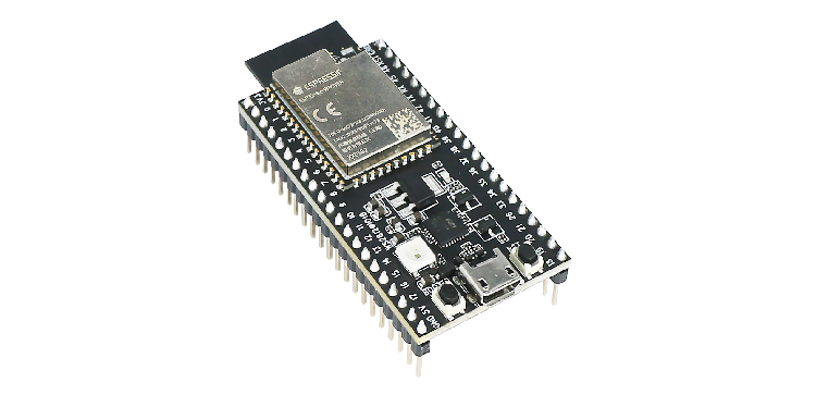
ESP32-S2-Saola-1
The ESP32-S2-Saola-1 is a development board for the ESP32-S2 SoC from Espressif, based on the following modules:
ESP32-S2-WROVER
ESP32-S2-WROVER-I
ESP32-S2-WROOM
ESP32-S2-WROOM-I
In this guide, we take ESP32-S2-Saola-1 equipped with ESP32-S2-WROVER as an example.
ESP32-S2-Saola-1
Features
ESP32-S2-WROVER - 4 MB external SPI flash + 2 MB PSRAM
USB-to-UART bridge via micro USB port
Power LED
EN and BOOT buttons
RGB LED (Addressable RGB LED (WS2812), driven by GPIO18)
Serial Console
UART0 is, by default, the serial console. It connects to the on-board CP2102 converter and is available on the micro-USB connector (J1).
It will show up as /dev/ttyUSB[n] where [n] will probably be 0.
I2S
ESP32-S2 has an I2S peripheral accessible using either the generic I2S audio driver or a specific audio codec driver (CS4344 bindings are available at the moment). The generic I2S audio driver enables using both the receiver module (RX) and the transmitter module (TX) without using any specific codec. Also, it’s possible to use the I2S character device driver to bypass the audio subsystem and write directly to the I2S peripheral.
Note
When using the audio system, sample rate and data width are automatically set by the upper half audio driver.
Note
The above statement is not valid when using the I2S character device driver. It’s possible to use 8, 16, 24, and 32-bit-widths writing directly to the I2S character device. Just make sure to set the bit-width:
$ make menuconfig
-> System Type
    -> ESP32-S2 Peripheral Selection
        -> I2S
            -> Bit Width
Configurations
All of the configurations presented below can be tested by running the following commands:
$ ./tools/configure.sh esp32s2-saola-1:<config_name>
$ make flash ESPTOOL_PORT=/dev/ttyUSB0 -j
Where <config_name> is the name of board configuration you want to use, i.e.: nsh, buttons, wifi…
Then use a serial console terminal like picocom configured to 115200 8N1.
adc
The adc configuration enables the ADC driver and the ADC example application.
ADC Unit 1 is registered to /dev/adc0 with channels 0, 1, 2 and 3 enabled by default.
Currently, the ADC operates in oneshot mode.
More ADC channels can be enabled or disabled in ADC Configuration menu.
This example shows channels 0 and 1 connected to 3.3 V and channels 2 and 3 to GND (all readings show in units of mV):
nsh> adc -n 1
adc_main: g_adcstate.count: 1
adc_main: Hardware initialized. Opening the ADC device: /dev/adc0
Sample:
1: channel: 0 value: 3061
2: channel: 1 value: 3061
3: channel: 2 value: 106
4: channel: 3 value: 99
audio
This configuration uses the I2S peripheral and an externally connected audio codec to play an audio file. The easiest way of playing an uncompressed file is embedding into the firmware. This configuration selects romfs example to allow that.
Audio Codec Setup
The CS4344 audio codec is connected to the following pins:
ESP32-S2 Pin |
CS4344 Pin |
Description |
|---|---|---|
33 |
MCLK |
Master Clock |
35 |
SCLK |
Serial Clock |
34 |
LRCK |
Left Right Clock (Word Select) |
36 |
SDIN |
Serial Data In on CS4344. (DOUT on ESP32) |
ROMFS example
Prepare and build the audio defconfig:
$ make -j distclean && ./tools/configure.sh esp32s2-saola-1:audio && make
This will create a temporary folder in apps/examples/romfs/testdir. Move
a PCM-encoded (.wav) audio file with 16 or 24 bits/sample (sampled at 16~48kHz)
to this folder.
Note
You can use this 440 Hz sinusoidal tone.
The audio file should be located at apps/examples/romfs/testdir/tone.wav
Build the project again and flash it (make sure not to clean it, just build)
After successfully built and flashed, load the romfs and play it:
nsh> romfs
nsh> nxplayer
nxplayer> play /usr/share/local/tone.wav
coremark
This configuration sets the CoreMark benchmark up for running on the maximum number of cores for this system. It also enables some optimization flags and disables the NuttShell to get the best possible score.
Note
As the NSH is disabled, the application will start as soon as the system is turned on.
crypto
This configuration enables support for the cryptographic hardware and
the /dev/crypto device file. Currently, we are supporting SHA-1,
SHA-224 and SHA-256 algorithms using hardware.
To test hardware acceleration, you can use hmac example and following output
should look like this:
nsh> hmac
...
hmac sha1 success
hmac sha1 success
hmac sha1 success
hmac sha256 success
hmac sha256 success
hmac sha256 success
cxx
Development environment ready for C++ applications. You can check if the setup
was successful by running cxxtest:
nsh> cxxtest
Test ofstream ================================
printf: Starting test_ostream
printf: Successfully opened /dev/console
cout: Successfully opened /dev/console
Writing this to /dev/console
Test iostream ================================
Hello, this is only a test
Print an int: 190
Print a char: d
Test std::vector =============================
v1=1 2 3
Hello World Good Luck
Test std::map ================================
Test C++17 features ==========================
File /proc/meminfo exists!
Invalid file! /invalid
File /proc/version exists!
efuse
This configuration demonstrates the use of the E-Fuse driver. It can be accessed
through the /dev/efuse device file.
Virtual E-Fuse mode can be used by enabling CONFIG_ESPRESSIF_EFUSE_VIRTUAL
option to prevent possible damages on chip.
The following snippet demonstrates how to read MAC address:
int fd;
int ret;
uint8_t mac[6];
struct efuse_param_s param;
struct efuse_desc_s mac_addr =
{
.bit_offset = 1,
.bit_count = 48
};
const efuse_desc_t* desc[] =
{
&mac_addr,
NULL
};
param.field = desc;
param.size = 48;
param.data = mac;
fd = open("/dev/efuse", O_RDONLY);
ret = ioctl(fd, EFUSEIOC_READ_FIELD, ¶m);
To find offset and count variables for related E-Fuse, please refer to Espressif’s Technical Reference Manuals.
gpio
This is a test for the GPIO driver. It includes one arbitrary GPIO. For this example, GPIO1 was used (defined by the board implementation). At the nsh, we can turn the GPIO output on and off with the following:
nsh> gpio -o 1 /dev/gpio0
nsh> gpio -o 0 /dev/gpio0
To use dedicated gpio for controlling multiple gpio pin at the same time or having better response time, you need to enable CONFIG_ESPRESSIF_DEDICATED_GPIO option. Dedicated GPIO is suitable for faster response times required applications like simulate serial/parallel interfaces in a bit-banging way. After this option enabled GPIO6 and GPIO5 pins are ready to used as dedicated GPIO pins as input/output mode. These pins are for example, you can use any pin up to 8 pins for input and 8 pins for output for dedicated gpio. To write and read data from dedicated gpio, you need to use write and read calls.
The following snippet demonstrates how to read/write to dedicated GPIO pins:
int fd; = open("/dev/dedic_gpio0", O_RDWR);
int rd_val = 0;
int wr_mask = 0xffff;
int wr_val = 3;

while(1)
  {
    write(fd, &wr_val, wr_mask);
    if (wr_val == 0)
      {
        wr_val = 3;
      }
    else
      {
        wr_val = 0;
      }
    read(fd, &rd_val, sizeof(uint32_t));
    printf("rd_val: %d", rd_val);
  }
i2c
This configuration can be used to scan and manipulate I2C devices. You can scan for all I2C devices using the following command:
nsh> i2c dev 0x00 0x7f
To use slave mode, you can enable ESP32S2_I2S_ROLE_SLAVE option. To use slave mode driver following snippet demonstrates how write to i2c bus using slave driver:
#define ESP_I2C_SLAVE_PATH  "/dev/i2cslv0"
int main(int argc, char *argv[])
  {
    int i2c_slave_fd;
    int ret;
    uint8_t buffer[5] = {0xAA};
    i2c_slave_fd = open(ESP_I2C_SLAVE_PATH, O_RDWR);
    ret = write(i2c_slave_fd, buffer, 5);
    close(i2c_slave_fd);
 }
i2schar
This configuration enables the I2S character device and the i2schar example app, which provides an easy-to-use way of testing the I2S peripheral, enabling both the TX and the RX for those peripherals.
I2S pinout
ESP32-S2 Pin |
Signal Pin |
Description |
|---|---|---|
33 |
MCLK |
Master Clock |
35 |
SCLK |
Bit Clock (SCLK) |
34 |
LRCK |
Word Select (LRCLK) |
36 |
DOUT |
Data Out |
37 |
DIN |
Data In |
After successfully built and flashed, run on the boards’s terminal:
nsh> i2schar
The corresponding output should show related debug information.
mcuboot_nsh
This configuration is the same as the nsh configuration, but it generates the application
image in a format that can be used by MCUboot. It also makes the make bootloader command to
build the MCUboot bootloader image using the Espressif HAL.
mcuboot_update_agent
This configuration is used to represent an MCUboot image that contains an update agent to perform over-the-air (OTA) updates. Wi-Fi settings are already enabled and image confirmation program is included.
Follow the instructions in the MCUBoot and OTA Update section to execute OTA update.
nsh
Basic NuttShell configuration (console enabled in UART0, exposed via USB connection by means of CP2102 converter, at 115200 bps).
nxlooper
This configuration uses the I2S peripheral as an I2S receiver and transmitter at the same time. The idea is to capture an I2S data frame using the RX module and reproduce the captured data on the TX module.
Receiving and transmitting data on I2S
The I2S will act as a receiver (master mode), capturing data from DIN, which needs to be connected to an external source as follows:
ESP32-S2 Pin |
Signal Pin |
Description |
|---|---|---|
33 |
MCLK |
Master Clock |
35 |
SCLK |
Bit Clock (SCLK) Output |
34 |
LRCK |
Word Select (LRCLK) Output |
36 |
DOUT |
Data Out |
37 |
DIN |
Data In |
The DOUT pin will output the captured data frame.
Note
The ESP32-S2 contains a single I2S peripheral, so the peripheral works on “full-duplex” mode. The SCLK and LRCK signals are connected internally and the TX module is set-up as slave and the RX as master.
nxlooper
The nxlooper application captures data from the audio device with receiving
capabilities and forwards the audio data frame to the audio device with
transmitting capabilities.
After successfully built and flashed, run on the boards’s terminal:
nsh> nxlooper
nxlooper> loopback
Note
loopback command default arguments for the channel configuration,
the data width and the sample rate are, respectively, 2 channels,
16 bits/sample and 48KHz. These arguments can be supplied to select
different audio formats, for instance:
nxlooper> loopback 2 8 44100
oneshot
This config demonstrate the use of oneshot timers present on the ESP32-S2.
To test it, just run the oneshot example:
nsh> oneshot
Opening /dev/oneshot
Maximum delay is 4294967295999999
Starting oneshot timer with delay 2000000 microseconds
Waiting...
Finished
ostest
This is the NuttX test at apps/testing/ostest that is run against all new architecture ports to assure a correct implementation of the OS.
qencoder —
This configuration demonstrates the use of Quadrature Encoder connected to pins
GPIO10 and GPIO11. You can start measurement of pulses using the following
command (by default, it will open \dev\qe0 device and print 20 samples
using 1 second delay):
nsh> qe
pm
This config demonstrate the use of power management.
You can use the pmconfig command to check current power state and time spent in other power states.
Also you can define time will spend in standby and sleep modes:
$ make menuconfig
-> Board Selection
    -> (15) PM_STANDBY delay (seconds)
       (0)  PM_STANDBY delay (nanoseconds)
       (20) PM_SLEEP delay (seconds)
       (0)  PM_SLEEP delay (nanoseconds)
Timer wakeup is not only way to wake up the chip. Other wakeup modes include:
EXT1 wakeup mode: Uses RTC GPIO pins to wake up the chip. Enabled with
CONFIG_PM_EXT1_WAKEUPoption.ULP coprocessor wakeup mode: Uses ULP RISC-V co-processor to wake up the chip. Enabled with
CONFIG_PM_ULP_WAKEUPoption.GPIO wakeup mode: Uses GPIO pins to wakeup the chip. Only wakes up the chip from
PM_STANDBYmode and requiresCONFIG_PM_GPIO_WAKEUP.UART wakeup mode: Uses UART to wakeup the chip. Only wakes up the chip from
PM_STANDBYmode and requiresCONFIG_PM_GPIO_WAKEUP.
Before switching PM status, you need to query the current PM status to call correct number of relax command to correct modes:
nsh> pmconfig
Last state 0, Next state 0

/proc/pm/state0:
DOMAIN0           WAKE         SLEEP         TOTAL
normal          0s 00%        0s 00%        0s 00%
idle            0s 00%        0s 00%        0s 00%
standby         0s 00%        0s 00%        0s 00%
sleep           0s 00%        0s 00%        0s 00%

/proc/pm/wakelock0:
DOMAIN0      STATE     COUNT      TIME
system       normal        2        1s
system       idle          1        1s
system       standby       1        1s
system       sleep         1        1s
In this case, needed commands to switch the system into PM idle mode:
nsh> pmconfig relax normal
nsh> pmconfig relax normal
In this case, needed commands to switch the system into PM standby mode:
nsh> pmconfig relax idle
nsh> pmconfig relax normal
nsh> pmconfig relax normal
System switch to the PM sleep mode, you need to enter:
nsh> pmconfig relax standby
nsh> pmconfig relax idle
nsh> pmconfig relax normal
nsh> pmconfig relax normal
Note: When normal mode COUNT is 0, it will switch to the next PM state where COUNT is not 0.
Note: During light sleep, overall current consumption of board should drop from 26ma (without any system load) to 3.5 mA on ESP32-S2 Saola-1. During deep sleep, current consumption of board should drop from 26 (without any system load) to 1.24 mA.
pwm
This configuration demonstrates the use of PWM through a LED connected to GPIO2.
To test it, just execute the pwm application:
nsh> pwm
pwm_main: starting output with frequency: 10000 duty: 00008000
pwm_main: stopping output
random
This configuration shows the use of the ESP32-S2’s True Random Number Generator with
entropy sourced from Wi-Fi and Bluetooth noise.
To test it, just run rand to get 32 randomly generated bytes:
nsh> rand
Reading 8 random numbers
Random values (0x3ffe0b00):
0000  98 b9 66 a2 a2 c0 a2 ae 09 70 93 d1 b5 91 86 c8  ..f......p......
0010  8f 0e 0b 04 29 64 21 72 01 92 7c a2 27 60 6f 90  ....)d!r..|.'`o.
rmt
This configuration configures the transmitter and the receiver of the
Remote Control Transceiver (RMT) peripheral on the ESP32-S2 using GPIOs 18
and 2, respectively. The RMT peripheral is better explained
here,
in the ESP-IDF documentation. The minimal data unit in the frame is called the
RMT symbol, which is represented by rmt_item32_t in the driver:
The example irtest can be used to test the RMT peripheral. Connecting
these pins externally to each other will make the transmitter send RMT items
and demonstrates the usage of the RMT peripheral:
nsh> irtest
$open_device(/dev/lirc0)
$open_device(/dev/lirc1)
$write_data(1) 16777229 16 16777235 23
$read_data(0,4)
16777229, 16, 16777235, 23
WS2812 addressable RGB LEDs
This same configuration enables the usage of the RMT peripheral and the example
ws2812 to drive addressable RGB LEDs:
nsh> ws2812
Please note that this board contains an on-board WS2812 LED connected to GPIO18 and, by default, this config configures the RMT transmitter in the same pin.
romfs
This configuration demonstrates the use of ROMFS (Read-Only Memory File System) to provide
automated system initialization and startup scripts. ROMFS allows embedding a read-only
filesystem directly into the NuttX binary, which is mounted at /etc during system startup.
What ROMFS provides:
System initialization script (
/etc/init.d/rc.sysinit): Executed after board bring-upStartup script (
/etc/init.d/rcS): Executed after system init, typically used to start applications
Default behavior:
When this configuration is used, NuttX will:
Create a read-only RAM disk containing the ROMFS filesystem
Mount the ROMFS at
/etcExecute
/etc/init.d/rc.sysinitduring system initializationExecute
/etc/init.d/rcSfor application startup
Customizing startup scripts:
The startup scripts are located in:
boards/xtensa/esp32s2/common/src/etc/init.d/
rc.sysinit- System initialization scriptrcS- Application startup script
To customize these scripts:
Edit the script files in
boards/xtensa/esp32s2/common/src/etc/init.d/Add your initialization commands using any NSH-compatible commands
Example customizations:
rc.sysinit - Set up system services, mount additional filesystems, configure network.
rcS - Start your application, launch daemons, configure peripherals. This is executed after the rc.sysinit script.
Example output:
*** Booting NuttX ***
[...]
rc.sysinit is called!
rcS file is called!
NuttShell (NSH) NuttX-12.8.0
nsh> ls /etc/init.d
/etc/init.d:
.
..
rc.sysinit
rcS
rtc
This configuration demonstrates the use of the RTC driver through alarms. You can set an alarm, check its progress and receive a notification after it expires:
nsh> alarm 10
alarm_daemon started
alarm_daemon: Running
Opening /dev/rtc0
Alarm 0 set in 10 seconds
nsh> alarm -r
Opening /dev/rtc0
Alarm 0 is active with 10 seconds to expiration
nsh> alarm_daemon: alarm 0 received
sdm
This configuration enables the support for the Sigma-Delta Modulation (SDM) driver which can be used for LED dimming, simple dac with help of an low pass filter either active or passive and so on. ESP32-S2 supports 1 group of SDM up to 8 channels with any GPIO up to user. This configuration enables 1 channel of SDM on GPIO5. You can test DAC feature with following command with connecting simple LED on GPIO5
nsh> dac -d 100 -s 10 test
After this command you will see LED will light up in different brightness.
sdmmc_spi
This configuration is used to mount a FAT/FAT32 SD Card into the OS’ filesystem. It uses SPI to communicate with the SD Card, defaulting to SPI2.
The SD slot number, SPI port number and minor number can be modified in Application Configuration → NSH Library.
To access the card’s files, make sure /dev/mmcsd0 exists and then execute the following commands:
nsh> ls /dev
/dev:
console
mmcsd0
null
ttyS0
zero
nsh> mount -t vfat /dev/mmcsd0 /mnt
This will mount the SD Card to /mnt. Now, you can use the SD Card as a normal filesystem.
For example, you can read a file and write to it:
nsh> ls /mnt
/mnt:
hello.txt
nsh> cat /mnt/hello.txt
Hello World
nsh> echo 'NuttX RTOS' >> /mnt/hello.txt
nsh> cat /mnt/hello.txt
Hello World!
NuttX RTOS
nsh>
spi
This configuration enables the support for the SPI driver.
You can test it by connecting MOSI and MISO pins which are GPIO11 and GPIO13
by default to each other and running the spi example:
nsh> spi exch -b 2 "AB"
Sending:    AB
Received:   AB
timer
This config tests the general-use purpose timers. It includes the 4 timers, adds driver support, registers the timers as devices and includes the timer example.
To test it, just run the following:
nsh> timer -d /dev/timerx
Where x in the timer instance.
twai
This configuration enables the support for the TWAI (Two-Wire Automotive Interface) driver.
You can test it by connecting TWAI RX and TWAI TX pins which are GPIO0 and GPIO2 by default
to a external transceiver or connecting TWAI RX to TWAI TX pin by enabling
the Device Drivers -> CAN Driver Support -> CAN loopback mode option and running the can example:
nsh> can
nmsgs: 0
min ID: 1 max ID: 2047
Bit timing:
  Baud: 1000000
  TSEG1: 15
  TSEG2: 4
    SJW: 3
  ID:    1 DLC: 1
ulp
This configuration enables the support for the ULP RISC-V core coprocessor. To get more information about LP Core please check ULP LP Core Coprocessor docs.
Configuration uses a pre-built binary in Documentation/platforms/xtensa/esp32s3/boards/esp32s3-devkit/ulp_riscv_blink.bin
which is a blink example for GPIO0. After flashing operation, GPIO0 pin will blink.
Prebuild binary runs this code:
#include <stdio.h>
#include <stdint.h>
#include <stdbool.h>
#include "ulp_riscv.h"
#include "ulp_riscv_utils.h"
#include "ulp_riscv_gpio.h"

#define GPIO_PIN 0

#define nop() __asm__ __volatile__ ("nop")

bool gpio_level_previous = true;

int main (void)
 {
    while (1)
        {
        ulp_riscv_gpio_output_level(GPIO_PIN, gpio_level_previous);
        gpio_level_previous = !gpio_level_previous;
        for (int i = 0; i < 10000; i++)
          {
            nop();
          }
        }

    return 0;
 }
watchdog
This config test the watchdog timers. It includes the 2 MWDTs, adds driver support, registers the WDTs as devices and includes the watchdog example.
To test it, just run the following:
nsh> wdog -i /dev/watchdogx
Where x is the watchdog instance.
To test the XTWDT(/dev/watchdog3) an interrupt handler needs to be implemented because XTWDT does not have system reset feature. To implement an interrupt handler WDIOC_CAPTURE command can be used. When interrupt rises, XTAL32K clock can be restored with WDIOC_RSTCLK command.