This board definition is a starting point for development with
ESP32-S3-LCD-1.28 and
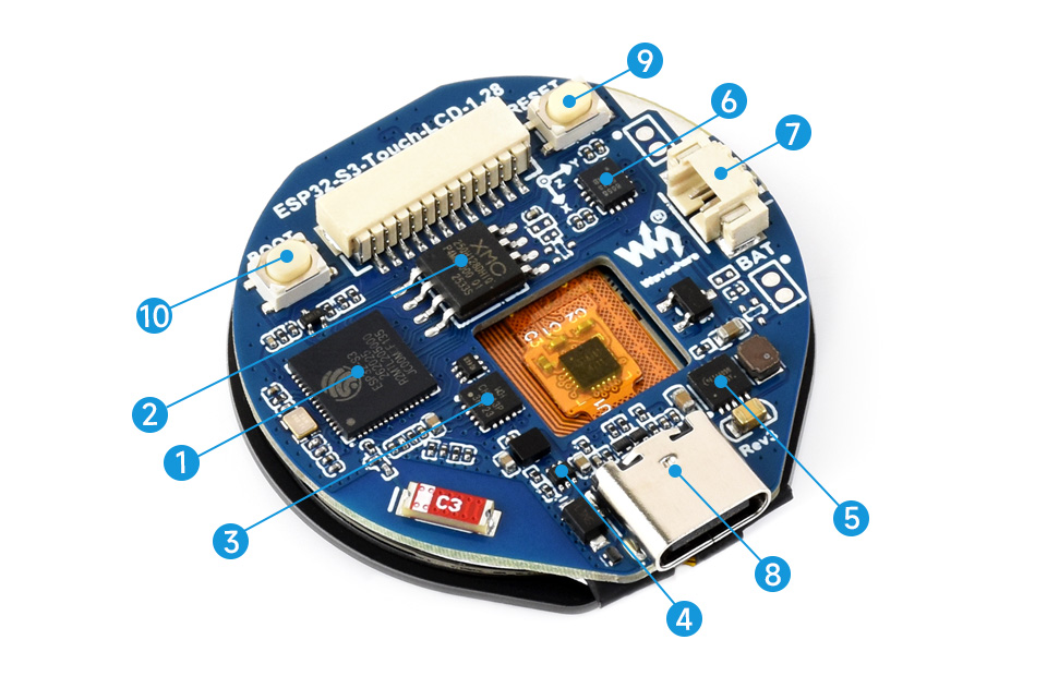
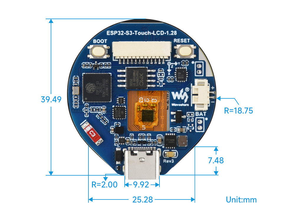
ESP32-S3-Touch-LCD-1.28
which are low-cost ($16/$22) open-source hardware designed by
WaveShare. High-performance Xtensa based
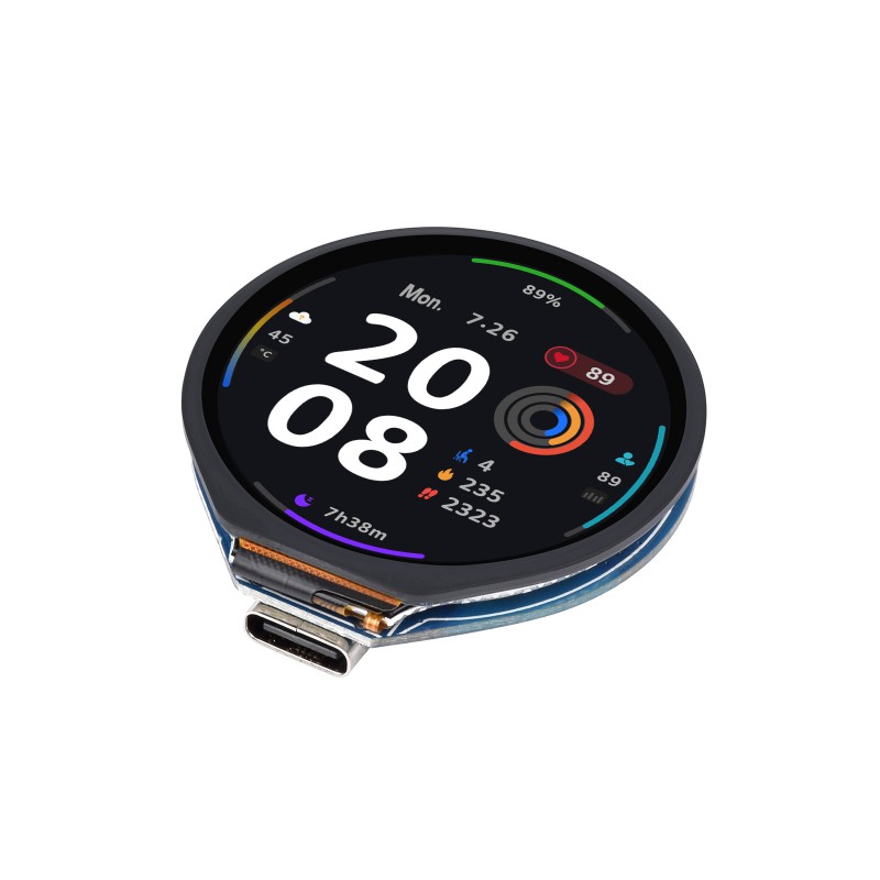
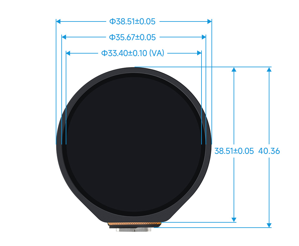
ESP32-S3 MCU, small size, onboard round 1.28” LCD display, capacitive touch
screen (Touch version only), Li-ion accumulator charge manager, 6-axis sensor
(3-axis accelerometer and 3-axis gyroscope), and quick module attachmend
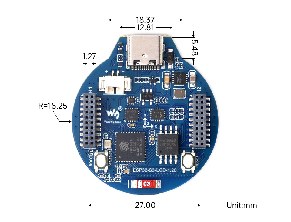
1.27mm connectors (non-Touch version only), makes it a perfect candidate
for integration into your projects and products quickly.
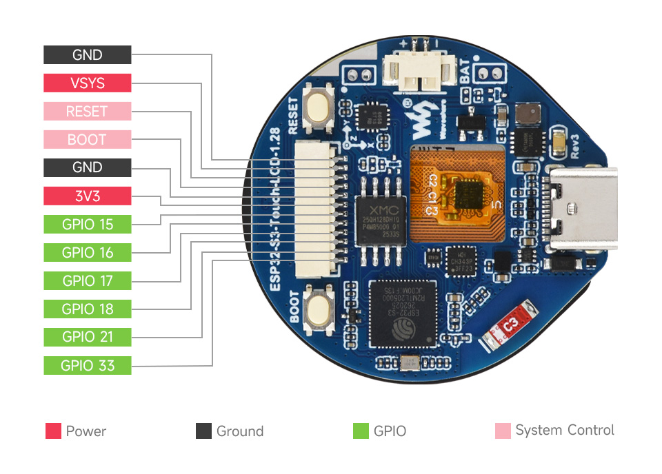
These boards are almost identical. Touch version has touch screen,
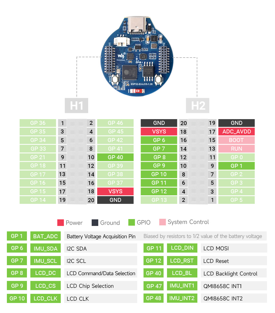
while non-Touch version has two connectors exposing more GPIOs at the bottom,
thus slightly different signal routes. See Pinouts and GPIO sections below
for details.
Because of that similarity, a single board definition is provided by NuttX,
while features and configuration details are build time Kconfig selectable:
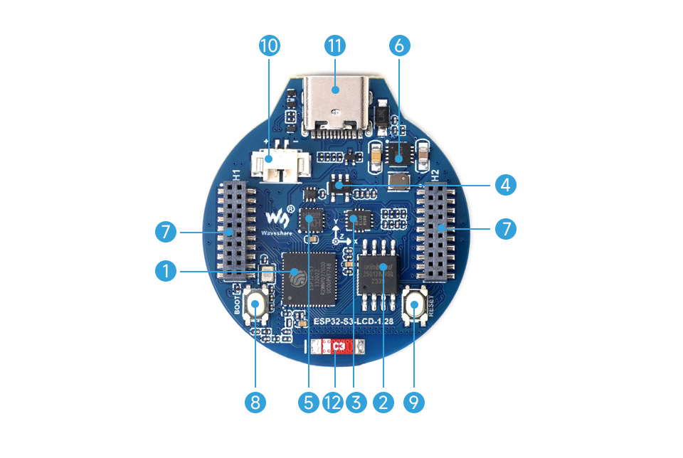
ESP32-S3-LCD-1.28 pinout on the picture above is different from
the schematics (picture has H2 rotated numbering but the signal
names are valid)! Schematics and table below shows correct data.
Issue is reported to vendor, we are waiting for the fix / update.
There are two buttons labeled BOOT and RESET (both are exposed on board
connectors):
RESET (active low) button is not available to the software and can be used
as manual hardware reset trigger.
BOOT button is connected to GPIO0. On reset/power-on it can be used to
trigger BootROM serial bootloader when pressed (active low) in order to
flash new firmware. After reset BOOT button can be used as software input.
UART0 is by default used for the serial console. It connects to the on-board
CH343P converter and is available on the USB-C connector that can be also used
for firmware flashing.
All of the available configurations provide basic testing utilities or serve
as an example starting point for your own projects.
Use them by running the following commands:
$ ./tools/configure.sh esp32s3-ws-lcd128:<config_name>
$ make flash -j ESPTOOL_PORT=<serial_port_device>
Notes:
<config_name> is the name of board configuration you want to use
(i.e. nsh, lvgl). Then use a serial console terminal like cu or
minicom configured to 115200 8N1.
<serial_port_device> is usually /dev/ttyUSB0 or /dev/cuaU0
depending on the OS you are using.
On BSD systems use GNU Make (gmake) in place of make.
This is a demonstration of the lvgl graphics library running on the
NuttX’s GC9A01A LCD driver. Demo will launch itself on boot
and you should see it on the screen right away.
This configuration uses the lvgldemo application.
Note
This configuration has CONFIG_ARCH_BOARD_ESP32S3_WS_LCD128_NOTOUCH
set. It selects LCD pins valid for the Non-Touch board variant.
Colors are invalid. Pixel format to be fixed. Work in progress.
Provides onboard QMI8658 IMU and internal ESP32S3 temperature
uorb sensors example. Sensors are registered under
/dev/urob/ and its data can be obtained with uorb_listener
application:
nsh> ls /dev/uorb
/dev/uorb:
sensor_accel0
sensor_gyro0
sensor_temp0

nsh> uorb_listener -n 10

Monitor objects num:3
object_name:sensor_temp, object_instance:0
object_name:sensor_gyro, object_instance:0
object_name:sensor_accel, object_instance:0
sensor_temp(now:144950000):timestamp:144950000,temperature:36.000000
sensor_temp(now:145960000):timestamp:145960000,temperature:37.000000
sensor_gyro(now:145960000):timestamp:145960000,x:-4.750000,y:-0.437500,z:0.156250,temperature:32.261719
sensor_accel(now:145960000):timestamp:145960000,x:0.031250,y:-0.088867,z:-1.051392,temperature:32.261719
sensor_temp(now:146970000):timestamp:146970000,temperature:37.000000
sensor_gyro(now:146970000):timestamp:146970000,x:-4.937500,y:-0.562500,z:0.218750,temperature:32.281250
sensor_accel(now:146970000):timestamp:146970000,x:0.031738,y:-0.088623,z:-1.046265,temperature:32.281250
sensor_temp(now:147980000):timestamp:147980000,temperature:37.000000
sensor_gyro(now:147980000):timestamp:147980000,x:-4.750000,y:0.031250,z:0.437500,temperature:32.273438
sensor_accel(now:147980000):timestamp:147980000,x:0.031005,y:-0.088745,z:-1.049683,temperature:32.273438
Object name:sensor_temp0, received:4
Object name:sensor_gyro0, received:3
Object name:sensor_accel0, received:3
Total number of received Message:10/10
This is a demonstration of the lvgl graphics library running on the
NuttX’s GC9A01A LCD driver. Demo will launch itself on boot and you
should see it on the screen right away.
This configuration uses the lvgldemo application.
Note
This configuration has CONFIG_ARCH_BOARD_ESP32S3_WS_LCD128_TOUCH
set. It selects LCD pins valid for the Touch board variant.
Colors are invalid. Pixel format to be fixed. Work in progress.
Touch screen driver (I2C/CST816S) is not yet implemented!
Work in progress.