Adafruit Feather RP2040
The Feather RP2040 is a general purpose RP2040 board supplied by Adafruit.
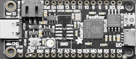
See the Adafruit website for information about Adafruit Feather RP2040.
Features
RP2040 microcontroller chip
Dual-core ARM Cortex M0+ processor, flexible clock running up to 133 MHz
264kB of SRAM, and 8MB of on-board Flash memory
Castellated module allows soldering direct to carrier boards
USB Host and Device support via type C connector.
Low-power sleep and dormant modes
Drag & drop programming using mass storage over USB
26 multi-function GPIO pins
2× SPI, 2× I2C, 2× UART, 3× 12-bit ADC, 16× controllable PWM channels
Accurate clock and timer on-chip
Temperature sensor
Accelerated floating point libraries on-chip
8 × Programmable IO (PIO) state machines for custom peripheral support
LiPoly Battery connector
Pin Mapping
Pads numbered anticlockwise from USB connector.
Pad |
Signal |
Notes |
|---|---|---|
1 |
Reset |
Pull to ground to reset the RP2040 processor. |
2 |
3.3V |
Power out to peripherals. |
3 |
3.3V |
Power out to peripherals. |
4 |
Ground |
|
5 |
GPIO26 |
ADC0 |
6 |
GPIO27 |
ADC1 |
7 |
GPIO28 |
ADC2 |
8 |
GPIO29 |
ADC3 |
9 |
GPIO24 |
|
10 |
GPIO25 |
|
11 |
GPIO18 |
|
12 |
GPIO19 |
|
13 |
GPIO20 |
|
14 |
GPIO1 |
Default RX for UART0 serial console |
15 |
GPIO0 |
Default TX for UART0 serial console |
16 |
GPIO6 |
|
17 |
GPIO2 |
|
18 |
GPIO3 |
|
19 |
GPIO7 |
|
20 |
GPIO8 |
|
21 |
GPIO9 |
|
22 |
GPIO10 |
|
23 |
GPIO11 |
|
24 |
GPIO12 |
|
25 |
GPIO13 |
|
26 |
VBUS |
Connected to USB +5V |
27 |
EN |
Pull to ground to turn off 3.3V regulator. |
28 |
VBAT |
Connected to LiPo battery 3.3V. |
The board has a STEMMA QT connector that is also connected to pins GPIO2 (I2C1 SDA) and GPIO3 (I2C1 SDA).
The board has a two pin JST PH socket that accepts a single 3.3V LiPo cell. The cell connected to this port can be charged by connecting the board to a USB power supply.
There are solder pads on the board that allow the addition of a 10-pin serial debug (SWD) connector.
Power Supply
The Raspberry Pi Pico can be powered via the USB connector, or by supplying +5V to pin 39. The board had a diode that prevents power from pin 39 from flowing back to the USB socket, although the socket can be power via pin 30.
The Raspberry Pi Pico chip run on 3.3 volts. This is supplied by an onboard voltage regulator. This regulator can be disabled by pulling pin 37 to ground.
The regulator can run in two modes. By default the regulator runs in PFM mode which provides the best efficiency, but may be switched to PWM mode for improved ripple by outputting a one on GPIO23.
Installation & Build
For instructions on how to to install the build dependencies and create a NuttX image for this board, consult the main RP2040 documentation.
Configurations
All configurations listed below can be configured using the following command in
the nuttx directory (again, consult the main RP2040 documentation):
$ ./tools/configure.sh adafruit-feather-rp2040:<configname>
audiopack
NuttShell configuration (console enabled in UART0, at 115200 bps) with support for NXPlayer audio player.
Pico Audio Pack support. See the following page for connection: https://shop.pimoroni.com/products/pico-audio-pack SD card interface is also enabled.
composite
NuttShell configuration (console enabled in UART0, at 115200 bps) with support for
CDC/ACM with MSC USB composite driver. conn command enables the composite
device.
displaypack
NuttShell configuration (console enabled in USB Port, at 115200 bps) supporting ST7789 video display.
See the following page for connection: https://shop.pimoroni.com/products/pico-display-pack
enc28j60
NuttShell configuration (console enabled in UART0, at 115200 bps) with support for ENC28J60.
ENC28J60 SPI ethernet controller supports:
IP address is configured by DHCP.
DNS address is 8.8.8.8 (CONFIG_NETINIT_DNSIPADDR)
NTP client is enabled.
ENC28J60 |
Raspberry Pi Pico W |
|---|---|
GND |
GND (Pin 3 or 38 or …) |
3.3V |
3V3 OUT (Pin 36) |
SI |
GP15 (SPI1 TX) (Pin 20) |
SCK |
GP14 (SPI1 SCK) (Pin 19) |
CS |
GP13 (SPI1 CSn) (Pin 17) |
SO |
GP12 (SPI1 RX) (Pin 16) |
INT |
GP11 (Pin 15) |
RESET |
GP10 (Pin 14) |
lcd1602
NuttShell configuration (console enabled in UART0, at 115200 bps) with support for LCD1602 Segment LCD Display (I2C).
PCF8574 BackPack |
Raspberry Pi Pico W |
|---|---|
GND |
GND (Pin 3 or 38 or …) |
VCC |
5V Vbus (Pin 40) |
SDA |
GP4 (I2C0 SDA) (Pin 6) |
SCL |
GP5 (I2C0 SCL) (Pin 7) |
nsh
Basic NuttShell configuration (console enabled in UART0, at 115200 bps).
nsh-flash
Basic NuttShell configuration (console enabled in UART0, at 115200 bps with SMART flash filesystem.
nshsram
NuttShell configuration (console enabled in UART0, at 115200 bps) with interrupt vectors in RAM.
smp
Basic NuttShell configuration (console enabled in UART0, at 115200 bps) with both ARM cores enabled.
spisd
NuttShell configuration (console enabled in UART0, at 115200 bps) with SPI SD card support enabled.
SD card slot |
Raspberry Pi Pico W |
|---|---|
DAT2 |
Not connected |
DAT3/CS |
GP17 (SPI0 CSn) (Pin 22) |
CMD /DI |
GP19 (SPI0 TX) (Pin 25) |
VDD |
3V3 OUT (Pin 36) |
CLK/SCK |
GP18 (SPI0 SCK) (Pin 24) |
VSS |
GND (Pin 3 or 38 or …) |
DAT0/DO |
GP16 (SPI0 RX) (Pin 21) |
DAT1 |
Not connected |
Card hot swapping is not supported.
ssd1306
NuttShell configuration (console enabled in UART0, at 115200 bps) with support for SSD1306 OLED display (I2C) test configuration.
SSD1306 |
Raspberry Pi Pico W |
|---|---|
GND |
GND (Pin 3 or 38 or …) |
VCC |
3V3 OUT (Pin 36) |
SDA |
GP4 (I2C0 SDA) (Pin 6) |
SCL |
GP5 (I2C0 SCL) (Pin 7) |
st7735
NuttShell configuration (console enabled in UART0, at 115200 bps) with support for ST7735 SPI LCD.
st7735 |
Raspberry Pi Pico W |
|---|---|
GND |
GND (Pin 3 or 38 or …) |
VCC |
5V Vbus (Pin 40) |
SDA |
GP15 (SPI1 TX) (Pin 20) |
SCK |
GP14 (SPI1 SCK) (Pin 19) |
CS |
GP13 (SPI1 CSn) (Pin 17) |
AO(D/C) |
GP12 (SPI1 RX) (Pin 16) |
BL |
GP11 (Pin 15) |
RESET |
GP10 (Pin 14) |
usbmsc
NuttShell configuration (console enabled in UART0, at 115200 bps) with support for USB MSC and CDC/ACM.
msconn and sercon commands enable the MSC and CDC/ACM devices. The MSC
support provides the interface to the SD card with SPI, so the SD card slot
connection like spisd configuration is required.
usbnsh
Basic NuttShell configuration using CDC/ACM serial (console enabled in USB Port, at 115200 bps).