Waveshare RP2040 LCD 1.28

The Waveshare RP2040 LCD 1.28 is a low-cost, high-performance MCU board designed by Waveshare based on RP2040 with onboard 1.28 inch LCD.

../../../../../_images/RP2040-LCD-1.28.jpg

Features

  • RP2040 MCU chip designed by Raspberry Pi in the United Kingdom

  • Dual-core Arm Cortex M0+ processor, flexible clock running up to 133 MHz

  • 264KB of SRAM, and 2MB of onboard Flash memory

  • Type-C connector, keeps it up to date, easier to use

  • Onboard 1.28-inch 240 x 240 resolution, 65K RGB IPS LCD display for clear color pictures

  • Lithium battery recharge/discharge header, suitable for mobile devices

  • All GPIOs are adapted through 1.27 pitch female headers (There are 30 pins in total, but some pins have been connected to the internal circuit, you need to pay attention when multiplexing, please refer to the wiki for details)

  • USB 1.1 with device and host support

  • Low-power sleep and dormant modes

  • Drag-and-drop programming using mass storage over USB

  • 2 x SPI, 2 x I2C, 2 x UART, 2 x UART, 4 x 12-bit ADC, 16 x controllable PWM channels

  • Accurate clock and timer on-chip

  • Temperature sensor

  • Accelerated floating-point libraries on-chip

  • 8 x Programmable I/O (PIO) state machines for custom peripheral support
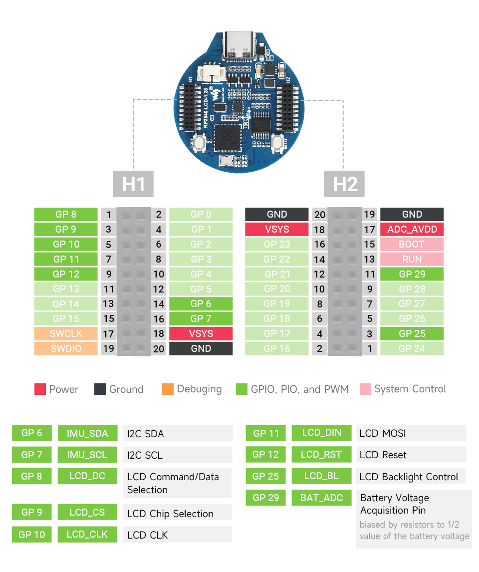
Serial Console

By default a serial console appears on pins 1 (TX GPIO0) and pin 2 (RX GPIO1). This console runs a 115200-8N1.

The board can be configured to use the USB connection as the serial console.

Buttons and LEDs

No user LED is provided.

A BOOT button, which if held down when pressing RESET or power is first applied to the board, will cause the RP2040 to boot into programming mode and appear as a storage device to a computer connected via USB. Saving a .UF2 file to this device will replace the Flash ROM contents on the RP2040.

Pin Mapping

Pad

Signal

Notes

2

GPIO0

Default TX for UART0 serial console

4

GPIO1

Default RX for UART0 serial console

Power Supply

The Raspberry Pi Pico can be powered via the USB connector, connecting a lithium battery through connector, or by supplying +5V to pin 18(VSYS). The board had a diode that prevents power from pin 18 from flowing back to the USB socket. Power through USB or VSYS will be charging the battery if connected. The schematic is available at RP2040-LCD-1.28-sch.pdf

Configurations

composite

NuttShell configuration (console enabled in UART0, at 115200 bps) with support for CDC/ACM with MSC USB composite driver.

nsh

Basic NuttShell configuration (console enabled in UART0, at 115200 bps).

nsh-flash

Basic NuttShell configuration (console enabled in UART0, at 115200 bps with SMART flash filesystem.

nshsram

NuttShell configuration (console enabled in UART0, at 115200 bps) with interrupt vectors in RAM.

smp

Basic NuttShell configuration (console enabled in UART0, at 115200 bps) with both ARM cores enabled.

spisd

NuttShell configuration (console enabled in UART0, at 115200 bps) with SPI configured.

usbmsc

NuttShell configuration (console enabled in UART0, at 115200 bps) with support for usbmsc.

usbnsh

Basic NuttShell configuration (console enabled in USB Port, at 115200 bps).

fb

NuttShell configuration (console enabled in USB Port, at 115200 bps) with support for gc9a01 and video framebuffer example.

lvgl

NuttShell configuration (console enabled in USB Port, at 115200 bps) with support for gc9a01 and LVGL demo (using lcd_dev).

README.txt

README
======

This directory contains the port of NuttX to the Waveshare RP2040 LCD 1.28.
See https://www.waveshare.com/wiki/RP2040-LCD-1.28 for information
about Waveshare RP2040 LCD 1.28.

NuttX supports the following RP2040 capabilities:
  - UART  (console port)
    - GPIO 0 (UART0 TX) and GPIO 1 (UART0 RX) are used for the console.
  - I2C
  - SPI (master only)
  - DMAC
  - PWM
  - ADC
  - Watchdog
  - USB device
    - MSC, CDC/ACM serial and these composite device are supported.
    - CDC/ACM serial device can be used for the console.
  - PIO (RP2040 Programmable I/O)
  - Flash ROM Boot
  - SRAM Boot
    - If Pico SDK is available, nuttx.uf2 file which can be used in
      BOOTSEL mode will be created.
  - Persistent flash filesystem in unused flash ROM

NuttX also provide support for these external devices:

  - BMP180 sensor at I2C0 (don't forget to define I2C0 GPIOs at "I2C0 GPIO pin assign" in Board Selection menu)
  - INA219 sensor / module (don't forget to define I2C0 GPIOs at "I2C0 GPIO pin assign" in Board Selection menu)
  - Pico Display Pack (ST7789 LCD)
    - RGB leds and buttons are not supported yet.
  - Pico Audio Pack (PCM5100A I2S DAC)
    - I2S interface is realized by PIO.
  - WS2812 smart pixel support

There is currently no direct user mode access to these RP2040 hardware features:
  - SPI Slave Mode
  - SSI
  - RTC
  - Timers

Installation
============

1. Download Raspberry Pi Pico SDK

  $ git clone -b 1.1.2 https://github.com/raspberrypi/pico-sdk.git

2. Set PICO_SDK_PATH environment variable

  $ export PICO_SDK_PATH=<absolute_path_to_pico-sdk_directory>

3. Configure and build NuttX

  $ git clone https://github.com/apache/nuttx.git nuttx
  $ git clone https://github.com/apache/nuttx-apps.git apps
  $ cd nuttx
  $ make distclean
  $ ./tools/configure.sh raspberrypi-pico:nsh
  $ make V=1

4. Connect Raspberry Pi Pico board to USB port while pressing BOOTSEL.
   The board will be detected as USB Mass Storage Device.
   Then copy "nuttx.uf2" into the device.
   (Same manner as the standard Pico SDK applications installation.)

5. To access the console, GPIO 0 and 1 pins must be connected to the
   device such as USB-serial converter.

   `usbnsh` configuration provides the console access by USB CDC/ACM serial
   devcice.  The console is available by using a terminal software on the USB
   host.

Defconfigs
==========

- nsh
    Minimum configuration with NuttShell

- nsh-flash
    NuttX shell with SMART flash filesystem.

- nshsram
    Load NuttX binary to SRAM

- smp
    Enable SMP mode. Both Core 0 and Core 1 are used by NuttX.

- ssd1306
    SSD1306 OLED display (I2C) test configuration
    Connection:
       SSD1306       Raspberry Pi Pico
           GND ----- GND            (Pin 3 or 38 or ...)
           VCC ----- 3V3 OUT        (Pin 36)
           SDA ----- GP4 (I2C0 SDA) (Pin 6)
           SCL ----- GP5 (I2C0 SCL) (Pin 7)

- lcd1602
    LCD 1602 Segment LCD Disaply (I2C)
    Connection:
    PCF8574 BackPack Raspberry Pi Pico
           GND ----- GND            (Pin 3 or 38 or ...)
           VCC ----- 5V Vbus        (Pin 40)
           SDA ----- GP4 (I2C0 SDA) (Pin 6)
           SCL ----- GP5 (I2C0 SCL) (Pin 7)
- spisd
    SD card support (SPI connection)
    Connection:
      SD card slot   Raspberry Pi Pico
       DAT2          (NC)
       DAT3/CS ----- GP17 (SPI0 CSn) (Pin 22)
       CMD /DI ----- GP19 (SPI0 TX)  (Pin 25)
       VDD     ----- 3V3 OUT         (Pin 36)
       CLK/SCK ----- GP18 (SPI0 SCK) (Pin 24)
       VSS     ----- GND             (Pin 3 or 38 or ...)
       DAT0/DO ----- GP16 (SPI0 RX)  (Pin 21)
       DAT1          (NC)
    * Card hot swapping is not supported.

- st7735
    st7735 SPI LCD support
    Connection:
      st7735         Raspberry Pi Pico
           GND ----- GND             (Pin 3 or 38 or ...)
           VCC ----- 5V Vbus         (Pin 40)
           SDA ----- GP15 (SPI1 TX)  (Pin 20)
           SCK ----- GP14 (SPI1 SCK) (Pin 19)
            CS ----- GP13 (SPI1 CSn) (Pin 17)
       AO(D/C) ----- GP12 (SPI1 RX)  (Pin 16)
            BL ----- GP11            (Pin 15)
         RESET ----- GP10            (Pin 14)

- enc28j60
    ENC28J60 SPI ethernet controller support
      - IP address is configured by DHCP.
      - DNS address is 8.8.8.8 (CONFIG_NETINIT_DNSIPADDR)
      - NTP client is enabled.
    Connection:
      ENC28J60       Raspberry Pi Pico
           GND ----- GND             (Pin 3 or 38 or ...)
           3.3 ----- 3V3 OUT         (Pin 36)
            SI ----- GP15 (SPI1 TX)  (Pin 20)
           SCK ----- GP14 (SPI1 SCK) (Pin 19)
            CS ----- GP13 (SPI1 CSn) (Pin 17)
            SO ----- GP12 (SPI1 RX)  (Pin 16)
           INT ----- GP11            (Pin 15)
         RESET ----- GP10            (Pin 14)

- displaypack
    Pico Display Pack support
    See the following page for connection:
      https://shop.pimoroni.com/products/pico-display-pack

- audiopack
    Pico Audio Pack support
    See the following page for connection:
      https://shop.pimoroni.com/products/pico-audio-pack
    SD card interface is also enabled.

- usbnsh
    USB CDC/ACM serial console with NuttShell

- usbmsc
    USB MSC and CDC/ACM support
    `msconn` and `sercon` commands enable the MSC and CDC/ACM devices.
    The MSC support provides the interface to the SD card with SPI,
    so the SD card slot connection like spisd configuration is required.

- composite
    USB composite device (MSC + CDC/ACM) support
    `conn` command enables the composite device.

License exceptions
==================

The following files are originated from the files in Pico SDK.
So, the files are licensed under 3-Clause BSD same as Pico SDK.

- arch/arm/src/rp2040/rp2040_clock.c
- arch/arm/src/rp2040/rp2040_pll.c
- arch/arm/src/rp2040/rp2040_xosc.c
  - These are created by referring the Pico SDK clock initialization.

- arch/arm/src/rp2040/rp2040_pio.c
- arch/arm/src/rp2040/rp2040_pio.h
- arch/arm/src/rp2040/rp2040_pio_instructions.h
  - These provide the similar APIs to Pico SDK's hardware_pio APIs.

- arch/arm/src/rp2040/hardware/*.h
  - These are generated from rp2040.svd originally provided in Pico SDK.