M5Stack Tab5
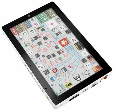
M5Stack Tab5 (front)
The M5Stack Tab5 is a portable HMI tablet built around the ESP32-P4 (dual RISC-V) application processor, paired with an ESP32-C6 companion module for Wi-Fi 6 / BLE / Thread connectivity over SDIO.
This NuttX port brings up the parts of the board that work with the upstream ESP32-P4 drivers only — no out-of-tree driver patches are required. The display and the other peripherals are not implemented yet; their pin assignments are documented below so they can be added later.
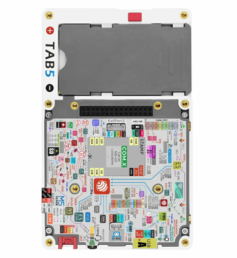
M5Stack Tab5 (rear): PCB, NP-F550 battery bay and M5-Bus connector
Features
ESP32-P4 (dual RISC-V @ 360 MHz), 16 MB flash, 32 MB Octal PSRAM
ESP32-C6-MINI-1U companion (Wi-Fi 6 / BLE / Thread) over SDIO2
5” MIPI-DSI IPS display, 720x1280 (ST7121 or ST7123 on supported units; older revisions use ILI9881C + GT911)
ES8388 audio codec + NS4150B speaker amp, ES7210 microphone array
SC2356 2 MP MIPI-CSI camera
BMI270 6-axis IMU, RX8130CE RTC, INA226 power monitor
Two PI4IOE5V6408 I2C IO expanders
NP-F550 battery via IP2326 charger, USB Type-C (OTG) + Type-A host
RS485 (SIT3088), microSD, M5-Bus 30-pin + Grove HY2.0-4P
Supported features
Peripheral |
Status |
|---|---|
UART / USB-Serial-JTAG |
Yes (NSH console on the USB-C port, |
I2C0 |
Yes ( |
PSRAM |
Yes (32 MB Octal) |
GPIO / BOOT button |
Yes |
IO Expander (both) |
Yes |
MIPI-DSI host |
Yes |
ST7121/ST7123 |
Yes |
Not yet implemented (pins and I2C addresses documented below):
Audio (ES8388 / ES7210), camera (SC2356)
INA226 power monitor — battery rail, 5 mOhm shunt (bus voltage = battery voltage; positive current = discharging, negative = charging)
RX8130CE RTC, microSD, ESP32-C6 Wi-Fi
Pin mapping
GPIO |
Function |
|---|---|
5 |
M5-Bus SCK |
6 |
PC_TX (debug UART) |
7 |
PC_RX (debug UART) |
8-15 |
ESP32-C6 SDIO2 bus (D3-D0, IO2, RST, CK, CMD) |
16, 17 |
M5-Bus general / PB_IN |
18 |
M5-Bus MOSI |
19 |
M5-Bus MISO |
20 |
RS485 TX |
21 |
RS485 RX |
22 |
LCD backlight enable (LEDA, via ME2212 boost) |
23 |
Touch interrupt (TP_INT; ST7121/ST7123 or GT911) |
26 |
I2S DSDIN (audio data to ES8388) |
27 |
I2S SCLK (audio bit clock) |
29 |
I2S LRCK (audio word clock) |
30 |
I2S / camera MCLK |
31 |
I2C0 SDA (touch, audio, IMU, RTC, power-mon, IO exp) |
32 |
I2C0 SCL |
34 |
RS485 direction (DE/RE) |
35 |
BOOT button |
36 |
Camera MCLK |
37 |
M5-Bus TXD0 |
38 |
M5-Bus RXD0 |
39 |
SD DAT0 (SPI MISO) |
40 |
SD DAT1 (SPI CS in microSD NAND mode) |
41 |
SD DAT2 (SPI SCK) |
42 |
SD DAT3 (SPI MOSI) |
43 |
SD CLK |
44 |
SD CMD |
52 |
M5-Bus PB_OUT |
53 |
Grove SDA |
54 |
Grove SCL |
Note
The MIPI-DSI data/clock lanes are dedicated MIPI pins (powered by
VDD_MIPI_DPHY) and are not part of the GPIO matrix. The panel has no
GPIO reset line (BSP_LCD_RST = NC); it is reset by the board power-on
reset. LCD_EN and TOUCH_EN are driven by IO expander 0x43
(P4 = LCD_EN, P5 = TOUCH_EN).
I2C device address map
Address |
Device |
|---|---|
0x10 |
ES8388 audio codec |
0x14 |
GT911 touch (older ILI9881 units) |
0x32 |
RX8130CE RTC |
0x40 |
ES7210 microphone array |
0x41 |
INA226 power monitor |
0x43 |
PI4IOE5V6408-1 IO expander (LCD_EN / TOUCH_EN) |
0x44 |
PI4IOE5V6408-2 IO expander (USB / Wi-Fi enables) |
0x55 |
ST7123 touch controller |
0x68 |
BMI270 IMU |
Chip revision
The Tab5 ships with ESP32-P4 revision v1.0. The nsh defconfig sets
CONFIG_ESP32P4_SELECTS_REV_LESS_V3=y accordingly. A harmless boot warning
is printed because the upstream default targets rev >= 3.0.
Display panel and touch controller
The Tab5 ships in two hardware variants, and they always come as a pair:
Variant |
Panel |
Touch controller |
|---|---|---|
Earlier units |
ILI9881C |
GT911 (I2C |
Later units |
ST7121 / ST7123 |
ST7123 (I2C |
The panels need different initialization tables and different display timings, so the wrong selection leaves the panel lit but black, and the wrong touch selection fails the bring-up with:
ERROR: failed to register ST7123: -5
Identify the board by scanning I2C0 with the nsh configuration. The
address that answers tells which variant is fitted, and therefore which
panel to select as well:
nsh> i2c dev -b 0 0x03 0x77
Select the panel with ESP32P4_TAB5_LCD_ST7121 (the default),
ESP32P4_TAB5_LCD_ST7123 or ESP32P4_TAB5_LCD_ILI9881C, and the touch
controller with ESP32P4_TAB5_TOUCH_ST7123 (the default) or
ESP32P4_TAB5_TOUCH_GT911, both under the board menu.
Both panels report their identification at boot, which confirms the
selection. The ILI9881C answers 98 81 in the first two ID registers:
ili9881c: panel ID 98 81 5c
gt911: product "911" (39 31 31 00) fw 1060
On the GT911 units the touch interrupt line has a pull-up to 3V3 that keeps the controller from scanning, so the board drives it low instead of using it as an interrupt. Contacts are picked up when the device is read.
Configurations
gpio
This is a test for the GPIO driver. It uses GPIO2 as output and GPIO3 as an interrupt pin.
At the nsh, we can turn the outputs on and off with the following:
nsh> gpio -o 1 /dev/gpio0
nsh> gpio -o 0 /dev/gpio0
We can use the interrupt pin to send a signal when the interrupt fires:
nsh> gpio -w 1 /dev/gpio1
The pin is configured as a rising edge interrupt, so after issuing the above command, connect it to 3.3V.
lvgl_demo
LVGL demo configuration with touch support.
Note
This configuration redirects the console to UART0 instead of the USB Serial/JTAG port and sets a custom entry point to open LVGL demo on screen.
$ ./tools/configure.sh esp32p4-tab5:lvgl_demo
$ make -j
lvgl_term
LVGL terminal configuration with touch support.
Note
This configuration starts the LVGL terminal on the panel as its entry
point, and it runs its own NSH on a pseudo-terminal. The console is kept
on the USB Serial/JTAG port (exposed as ttyACM on the host), which
carries the system log.
$ ./tools/configure.sh esp32p4-tab5:lvgl_term
$ make -j
nsh
Basic NuttShell configuration (console enabled over the USB Serial/JTAG port,
exposed as /dev/ttyACM0 on the host). Brings up the I2C0 bus.
python
This configuration enables the Python for ESP32-P4 on Tab5. Please refer to the Python Interpreter page.
sdmmc_spi
This configuration is used to mount a FAT/FAT32 SD Card into the OS’ filesystem. It uses SPI to communicate with the SD Card, defaulting to SPI3.
The SD slot number, SPI port number and minor number can be modified in Application Configuration → NSH Library,
however those are fixed by board design.
The bringup process will automatically mount the SD Card to /mnt if SD Card is present.
To manually mount the SD Card, make sure /dev/mmcsd0 exists and then execute the following commands:
nsh> ls /dev
/dev:
console
mmcsd0
null
ttyS0
zero
nsh> mount -t vfat /dev/mmcsd0 /mnt
This will mount the SD Card to /mnt. Now, you can use the SD Card as a normal filesystem.
For example, you can read a file and write to it:
nsh> ls /mnt
/mnt:
hello.txt
nsh> cat /mnt/hello.txt
Hello World
nsh> echo 'NuttX RTOS' >> /mnt/hello.txt
nsh> cat /mnt/hello.txt
Hello World!
NuttX RTOS
nsh>
Building and flashing
$ ./tools/configure.sh esp32p4-tab5:nsh
$ make -j
The NuttX image must be flashed at offset 0x2000 (the SIMPLE_BOOT
application offset for the ESP32-P4):
$ esptool.py -c esp32p4 -p /dev/ttyACM0 -b 921600 write_flash 0x2000 nuttx.bin
Then open the console:
$ picocom -b 115200 /dev/ttyACM0
nsh>